Home › Forums › Percolator Tube Amp Forum › Percolator FAQ & Support › Voltages off in Percolator…
Tagged: Percolator troubleshooting
- This topic has 7 replies, 1 voice, and was last updated 6 years, 1 month ago by
brach.
-
AuthorPosts
-
brach
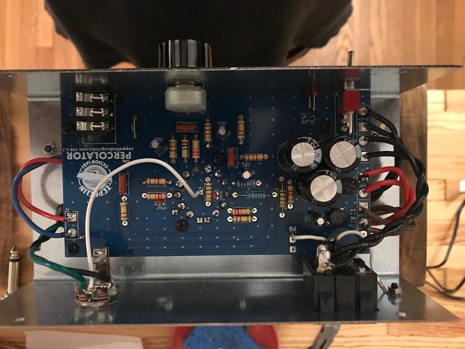
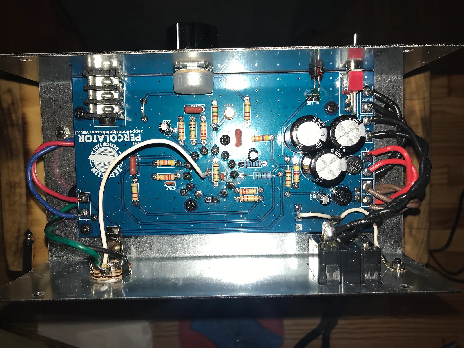
ModeratorI’m starting this thread to help troubleshoot a customer’s Percolator. He contacted us outside this forum about his build issue…i’m re-posting it here.
He says:
“Hi, I’m enjoying putting the head together to match the cab. I finished up the soldering today, but the amp isn’t working. I was able to power it up (LED goes on) but I’m getting some voltage abnormalities I’m hoping you can help me with. I went through the checklist in the manual and am getting high or no voltages. For instance, TP1 189, TP4 189, TP9 179, TP11 179. I’m most concerned that TP7 = 0 volts, and TP5 = 0 volts. I went back and checked every and it appear I got everything right. I touched up some solder points, plugged it back in and got nothing. The LED no longer turns on and I am not getting any voltage at the power receptacle with the amp turned off. It also sparked at the lug on the power receptacle where the ground is attached. Please help! I have attached photos for reference. Thanks!”
“Just a quick follow-up. The fuse is blown and I retested the resistance. R1 and R7, which are both supposed to be 1k5 are only .75k each. R4 is 838R not 820R as posted. However, even replacing the fuse I don’t think solves the initial issues I had. Thanks again for the assistance!”


brach
ModeratorMy response:
Thanks for the photos. It’s always helpful to get a visual of what we’re talking about.
R1 and R7 are basically in parallel with each other so they should measure around 750 ohms each. And that’s fine if R4 is a few ohms off, it’s still within a it’s 5% tolerance.
You said it sparked at the ground terminal, but can you tell where it sparked to? There was/is some short of short against the ground terminal there….was a strand of wire touching it somehow? It’s important to know why that happened so you can ensure it won’t happen again. Please replace the fuse with a 1 amp / 250V fast blow fuse….nothing bigger!
The voltages you shared from your test points indicate that the tube isn’t installed…is it? If it is, then please tighten
all the tube sockets to ensure all the pins are making good contact.
Keep me posted on your progress.
-BrachDaniel
GuestThanks for the response, Brach. It just sparked on the ground lug only – it didn’t notice to spark to anywhere else. The tube is installed. I’ll try tightening the sockets. The tube definitely heated up, but perhaps I loosened the contacts too much when I installed it. I’ll replace the fuse this evening and let you know how it works. Thanks!
brach
ModeratorIf you can’t figure out where the current in the spark went to then double and triple check under the board and all around for any stray wires or tiny solder balls or anything that could cause something like that. That’s probably not something you want happening very often. As I understand it, the amp was on for a while before the fuse blew. Is this correct?
It sounds like your problem is the tube socket pins are too loose. If it was making contact you should be getting at least some voltages on the cathodes of those tube sections (TP5 and 7).
Keep me posted.
Good luck!
-Brach
PS make sure you clean the black burnt area on the board and IEC jack…it’s conductive and cause arcing in the future. Rubbing alcohol on a q-tip works pretty well for this.Daniel
GuestIt was the tube sockets. Once I tightened those up, the amp works! The only thing that is not working is the LED. It is reading about 12 volts, which is way off. I re-soldered it, but it’s still around 12 volts.
brach
ModeratorThat’s great that it’s working now!
Are you saying that TP3 has 12v on it? If so, it appears the LED has been damaged…probably by the spark. It needs to be replaced. You might also want to check TP2. Also check to see if there is any AC voltage on TP2. It’s good to make sure other components weren’t damaged as well.
Here’s a method that makes it easier to replace the LED with out removing the board… Clip the old LED off at the board and mount the new LED in the chassis socket and run jumper wires down to the pads on the board. To do this, cut the new LED’s leads fairly short and bend little hooks in them. Bend hooks in the jumper wires too. Hook the two hooks together (the LED lead hook and the wire hook) and bend them together with your pliers and then solder over the connection. You can use some hot glue or something to affix the LED to the chassis if it needs it.
Let me know if you have any questions.
Good luck.
-BrachDaniel
GuestWorks great. Thanks for the help! I sent along some pics through the reverb messages.
brach
ModeratorI’m glad to hear that!
The amp and cabinet look great! Good work! Thanks for the pictures.
-Brach -
AuthorPosts


