- Your cart is empty
- Continue Shopping
Home › Forums › Quaverato Forum › Quaverato FAQ & Support › Depth not how it should be…
- This topic has 30 replies, 2 voices, and was last updated 2 years, 6 months ago by
yelemusic.
-
AuthorPosts
-
brach
ParticipantThank you for the videos and audio. All this is reiterating the fact that the high side is not tremoloing the audio, and the low side is. If the high side was working correctly then your Quaverato would sound just like the one in the videos.
There is almost certainly not a problem with the pots, but you can test this by measuring the voltage on the center pin to see if it’s getting from 0 to 5 volts. The transistor is not bad because you are telling me the high LED is pulsing. If the transistor was bad then it wouldn’t work. We’ve already established that the LDR is working, at least somewhat. You can do some more tests to ensure that the resistance of the LDR gets up to at least 1M ohms or so when it is in complete darkness. Right now, it seems like the only potential cause for this is that the high optocoupler is not sealed well and is letting some light in, causing the resistance to remain low across the LDR, so it never gets to compete darkness (up to 1M ohms across it). But i’ve already asked you to seal the optocoupler well and i’m assuming you’ve already done this.
You can test the optocoupler (with the power off) by measuring the resistance across it’s pins in the darkness. You can test if it’s sealed well by shining a flashlight on it to see if the resistance changes. The resistance should get much higher than 1k7 ohms in the complete darkness. Test both LDRs this way to ensure they are both behaving the same.
-Brachyelemusic
ParticipantHi Brach, sorry for the late reply, I was out of town for a few days.
I just checked the pots, they all seem to be fine, going from 0 to 5V, except for th Volume pot, which doesn’t show any voltage. Still working though, so that’s probably fine.
Both LDRs show a resistance of 1,8M in complete darkness. I taped black tape across it, and even shining a light directly onto them didn’t affect it. So I can safely say that they are not leaky.
I attached a video that shows how the LEDs behave depending on the position of the mix dial. It seems inconsistent. One would assume that both LEDs would work in the same but opposite way. But while the low LED flashes on the “low” side of the dial, and goes steady towards “hi”, the high LED only flashes in the middle position, goes steady in the dark position, and goes completely dark when the dial is all the way at “hi”. Sometimes it’s on though, when on “hi”, sometimes it’s not, so that’s another weirdness. So either it’s (from lo to hi) stead-flashing-off, or sometimes it’s steady-flashing-steady.
I tested for bad solder joints but so far I couldn’t determine what makes it go steady or of when the dial is on “hi” position.
http://www.falckenberg.com/downloads/Quaverato/IMG_8773.MOV
http://www.falckenberg.com/downloads/Quaverato/IMG_8775.MOVAlso, in one of the previous videos I showed the erratic behaviour of two pots. Could this be caused by some other fault somewhere else in the circuit? Measuring their voltage seemed fine, no erratic jumps, but as shown in the video they don’t behave that way.
This is getting frustrating 🙁
I could redo the optocoupler, or use a readymade one (I happen to have a silonex nsl-32 and a VTL5C2 lying around somewhere. Could any of these work instead?), but I have a feeling that won’t help, as they seem to be fine by the looks of it. The fault has to be elsewhere…
Could the TL074 be the culprit? Just asking, because it’s soldered in without a socket, so maybe it got too hot. I did take great care not to overheat it, but one never knows… Or the microcontroller? If this thing controls the optocouplers, maybe it’s faulty.ParticipantThank you for the videos, although I wasn’t able to see the second video…it seems to be a dead link.
But from the first video, I can see the problem seems to be with the LED, not the LDR (thank you for testing those resistances).
This is a really weird problem that I’ve never seen before. The issue has to be with either the LED or the driving circuit or with the microcontroller.
So to start on the top of the list, could you please measure the high side optocoupler LED with your diode tester on your multimeter (with the power off)? Just compare it with the low side LED to see if it’s the same. I expect it is.
If it passes that test, lets try to test Q1 (with the power on). Could you please turn the depth knob all the voltage on all the pins of Q1 and compare them with the voltages on the same pins of Q2? Then turn the depth knob all the way up (clockwise) and do the same thing. Keep the LFO rate relatively slow during this test so you can see the voltage changing. The voltage should be changing in relation to the LFO rate, so compare how the changing voltage on the pins of Q1 compare to the changing voltage on the same pins of Q2. Use the DC voltage setting on your meter to measure these. If both the transistors seem to be behaving the same then the problem might be with your microcontroller. But first please ensure that R14 is soldered correctly and is really 10K ohms in value. Then make sure pin 15 of the microcontroller is soldered well and it is seated well in the socket. If all that is good then you may need to re-flash the microcontroller. You’ll have to get a USBTiny programmer for that. We have the software on our website that you can download for free. After you do all these tests, let me know what you find.
-Brach
PS it doesn’t hurt to resolder all the pins on the components that I mentioned here…sometimes bad solder joints can look good.ParticipantOh, sorry. Here it is again. Let’s hope it works now:
ParticipantHi Brach,
let’s see:
So I checked the LEDs, they appear to be fine with the diode tester.
R14 is also fine.
I did reflow some of the solder joints, especially those of the micro controller, pin 15 looks good, all legs are properly seated.Transistors:
Depth all the way down, mix 50/50
Q1 pin1 no voltage, Q2 no voltage
pin2 ca 700mV, both sides
Q1 pin3 no voltage, Q2 022mVDepth up, Mix 50/50
Q1 pin1 no voltage, Q2 pin1 no voltage
Q1 pin2 fluctuating between ca 150 and 700mV, Q2 pin2 between 0 and ca 700mV
Q1 pin3 two random numbers followed by OL, Q2 same.second measurement, because I got suspicious:
Depth @ zero, mix 50/50
pin1 no voltage on both sides
pin2 again 700mV on both sides
Q1 pin3 041mV, Q2 022mVDepth full, mix 50/50
Q1 pin1 zero mV, Q2 pin1 zero mV
Q1 pin2 250-700mV, Q2 pin2 0-700mV
Q1 pin3 as before two random numbers followed by OL, Q2 pin3 same.My multimeter is a fairly inexpensive one, so it’s certainly not the most accurate, but it seems to me, that Q1 and 2 do indeed behave differently.
As the mix dial isn’t exactly precise either, I do consider the possibility that the difference in voltage between Q1 and 2 might also have to do with mix knob not exact in the middle, but I tried to set it so both LEDs flash the same.The random numbers on pin 3 seem funny to me, but since they occur on both Q1 and 2 I assume that’s probably fine. With depth all the way down the apparent difference between Q1 and 2 seems to be the voltage on pin 3, which is in fact absent on Q1 (second measurement was different. God knows why).
With Depth up both Q1 and 2 also behave differently, both go up to 700mV, while only Q2 goes all the way down to zero.So, without knowing much about anything, looking at these measurements I get the feeling that Q1 is funky. I might get a new set of those, and replace them. This time I’ll be using sockets though, as it makes things a lot easier.
Do you agree with my conclusion?Maybe I’m just trying to ignoring the uncomfortable third option, which might indeed be a faulty microcontroller. I’ve seen that your software is PC only, but I’m on Mac. So I’d have to find a PC for this purpose first. Well, let’s hope it doesn’t come to this.
But I have to say, as annoying as all of this is, it’s also great fun. I feel a bit like Sherlock Holmes 🙂
Thanks a LOT for your help 🙂
ParticipantThat is very good information. This seems to point to the microcontroller (uC) because the signal getting from the uC to the high side transistor never gets down to 0 volts when the depths is up (unlike the low side). For some reason the pwm seems to never turn all the way off.
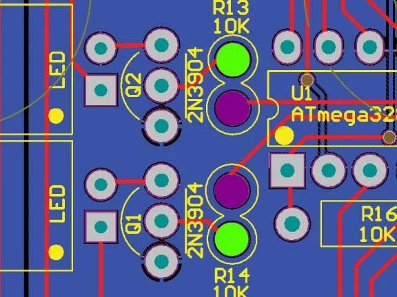
The real test is to find out how it behaves when the uC’s signals are switched between the high and low sides. You can try this by lifting one leg of R14 and R13.
https://zeppelindesignlabs.com/wp-content/uploads/2023/10/zeppelin_design_labs_quaverato_pcb-jpg.webp
In the pcb graphic, unsolder the green dots. Just leave the end of the resistors floating in the air while the other legs are still attached to the board on the purple dot. Find some very thin wire (I use “wire wrap” wire for these types of things) and run a jumper from the floating lead of R13 to the green pad of R14…and run another jumper from the floating lead of R14 to the green pad of R13.
Now turn on the power and test the optocoupler LEDs. If the problem is with the uC then the low led will start behaving like the high led used to, and the high led will start behaving like it’s supposed to.
If the problem is with the transistor (Q1) then the high led will misbehave the way it always has, and the low led will continue behaving correctly.
Let me know what you find out.
-Brach
ps I should have had you measure the resistance of R13 and R14 first to ensure they are really 10k or at least the same resistance value. So do that before you unsolder anything. If they measure different then unsolder one lead and re-measure them.ParticipantHi Brach,
so I reversed the resistors as you said (BTW they both measure a solid 10k), and now the low signal doesn’t shut off, just like the high signal before the change. So it seems that the problem has swapped sides. The mix knob still behaves the same way though, as in no effect in the fully high position.
In fully low position the high frequ band pulsates nicely, while the low portion rings through steadily.
Mix middle gives the greatest effect, while the low signal still bleeds through, albeit less than in full low.
Full high position no effect, however it sounds like the low frequencies get filtered out.
Concluding: The problem seems to be with the low frequency band after the swap.Hard to describe, even harder to compare between before and after, as it’s been a few days. Good thing I have made these videos 🙂
What I’m gonna do, is swapping the transistors anyway, just to make sure those are Ok. And I’ll be using sockets, so I won’t risk frying them. Also I’m going to undo the capacitor swap and put in fresh ones.
I’ll report back once I’ve done this.
But if I understand you correctly, all of this points towards a problem with the microcontroller. Not happy about this, cos I don’t really know how all that flashing business works, plus I don’t use a Windows PC…So if that’s the case, shouldn’t that fall under warranty, and thus warrant a replacement uC?
I bought the kit from floating point audio in France. Should we talk to them?ParticipantSo this conclusively tells us that the uC is the culprit. There’s no need to swap the transistors and please do not use sockets on them. Sockets have a tendency to become unstable over time, causing more problems down the road.
Unfortunately, this isn’t a warranty issue because the uC was most likely damaged in this way from static electricity in assembly. We do a pre-flight test on all these microcontrollers before they are shipped, so I can say it was working when we shipped it. We do sell replacement microcontrollers, if you don’t have a way to flash one. But if you are able to borrow a PC and get a usbtiny programmer (available many places online), the flashing procedure is very easy to do. We give step-by-step instructions in the updater app (press the “?” in the app window).
But all this being said, please contact me at info “at” zeppelindesignlabs.com and we can work with you to figure this out.
-BrachParticipantOk, thanks. Not so good news 🙁
But I won’t touch the ICs now 🙂I did take care not to hurt the uC with any sort of static charge during assembly, regularly touched “earth”, and only put it in once everything else was done. But hey, Sh!t happens I suppose 🙁
How much would a new uC be? And could it be ordered from France, or only from the US?
Will have to check if a friend happens to have a PC handy.
I’ll contact you via mail in the next few days. Thanks for your help!
ParticipantSorry for the bad news. Static electricity is very sneaky. Over the years I’ve damaged several microcontrollers by what I can only assume is static electricity. These IC’s can only handle at most 13 volts on a pin, but a static discharge isn’t even detectable by our senses until it is over 1000 volts…so they are really easy to damage without knowing it. And most of the time it doesn’t completely kill the chip, it only damages part of its functionality.
Unfortunately, these flashed uCs are only available from us directly, not any of our distributors.
But yes, please contact me via email and we’ll discuss this.
-BrachParticipantHi Brach,
I just sent you an Email as you suggested. It took me a while, been pretty busy the last few days.
Just so you know, that you’ve got mail 🙂
Thanks, EikoParticipantI’m sorry, I don’t think it got to us…could you please try to send it again: info”at”zeppelindesignlabs.com (change the “at” to the @ symbol).
Thanks.
-BrachParticipantHi Brach, I tried again. Let’s hope my Emails don’t get filtered out by your Spam filter. Hm… Please let me know, if it arrived this time.
Thanks, EikoParticipantHi Brach, don’t know if you received my last EMail. Maybe the spam filter caught it gain.
Anyway, flashing of the microcontroller did work a treat, and now my Quaverato is wobbling away as intended!
So, thanks once again for your great help!
And for those who might be following this thread: I can only say the best about zeppelindesignlabs and Brach, who did an exceptional job guiding ne through the process of troubleshooting my pedal!
I am one happy customer 🙂Participant(I’m sorry about my spam filter!)
That’s great to hear! I’m so glad it’s up and working now.
I hope you enjoy your Quaverato for years to come!
Take care.
-Brach -
AuthorPosts