- Your cart is empty
- Continue Shopping
Home › Forums › Quaverato Forum › Quaverato FAQ & Support › loss of volume
- This topic has 21 replies, 2 voices, and was last updated 2 years, 11 months ago by
brach.
-
AuthorPosts
-
pmjennings
ParticipantAll the voltage tests are done with power on. The meter is trustworthy. It’s just a no-frills unit without the continuity test function. Any inconsistencies are more likely caused by me. I’ve checked everywhere for shorts but all the solder joints are fine. Nothing is touching anything it shouldn’t. I’ve checked all the voltages again and here’s where it currently stands. Pin 5 of U2 is 2.4v. R28 is .45v. With bypass LED on, both optocoupler LEDs read 0v on the square pads. R7 and R8 also read 0 volts. I cut holes to check and there is no light. So, there is no voltage passing through that circuit. All other voltages read as the diagram in the troubleshooting guide illustrates. Do you think U1 is not working properly? There is zero output when hooked up to guitar and amp wether in bypass or normal. I hope you have a clue, because I’m stumped.
Thanks,
Peterbrach
ParticipantI’m glad you have confidence in your meter. Do you have as much confidence in your meter as in your ability to read it correctly (if it’s one of those analog meters)? I know for me those analog meters can be confusing.
I was referring to the relay continuity tests…when I was asking about power on or off, not voltage tests. Please let me know about this.
The voltage on R28 is of no consequence because C17 is removed.
The voltage on pin 5 of U2 is not off enough to keep signal from passing through that opamp.
If the optocoupler’s LEDs are not lighting up, then that would cause no signal to pass through the pedal when the bypass LED is on (when the effect is engaged). It would be unlikely that both optocoupler LEDs are not working, so are you sure this is happening? Either way, as I said earlier, you have more than one issue going on here because you are still not getting signal through the pedal when the bypass LED is off (the effect is bypassed). This is a much bigger issue than the previous one. The signal path is very simple in the bypass circuit….from the input jack tip, through the relay, to the output jack tip. If you are getting signal into the pedal and it really is not passing through to the output jack (when the effect is bypassed) then it can only be 1 (or 2) of 2 things: either there is a bad or broken connection somewhere (most likely a bad solder joint) or the relay isn’t working correctly. In conjunction with your meter testing this circuit, also please actually try it out with a real guitar signal (it’s important to try it both ways).
This problem (of the pedal not bypassing any signal) suddenly started when you re-flowed the solder joints and removed C17, correct? So it stands to reason that something you did in that process is causing this. Check all those connections that you touched up with the soldering iron. Make sure the input and output jacks are soldered correctly (re-flow them). Make sure the remaining pads (and traces) of C17 are not shorted to ground (see if the output jack tip is connected to ground…continuity test this). Is the relay really switching? You can test this with your continuity tester by following this image:
https://zeppelindesignlabs.com/wp-content/uploads/2023/06/relay-jpg.webp
The red lines represent the continuity you should have when the effect is engaged, and the blue lines represent the continuity you should have in bypass. Make sure you are testing the correct pins. This picture is taken from the top of the board, but it’s symmetrical so the bottom of the board is the same.
Please take the time to go through (and do) EACH of these things I’ve listed here in this post, until you find the problem. Let me know what you find.
-BrachParticipantProgress! I went through all your suggestions, and they were helpful. The results of the relay continuity test were just as the diagram showed. So, I checked the traces. The trace from the output jack to the relay goes through one of the pads of C17! When I pulled C17, both pads came off with it, so that broke the connection. After running a jumper wire from the output tip to the relay, the pedal again bypasses sound normally. However, as there is still no output in tremolo mode, I’m back to where I started.
I think the problem has to be the lack of voltage getting to the optocouplers. I tried to map the traces to see where those 5 volts @ R7/R8 originate from, but it’s too hard to see the traces with a populated board. Is there a diagram available that maps those traces? My board is version 8.3. I think this could make troubleshooting this issue easier. Or, can I just run a jumper wire from any 5v source to R7? I was going to try this anyway as a test, but I wanted to touch base with you first.
Thanks so much for your patience,
Peter
ParticipantExcellent! Great work fixing that. Now we can work on the original problem.
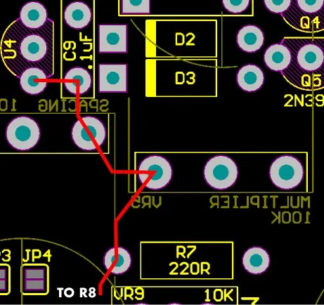
Yes, the place to start is with the optocoupler circuit. Right now, the only thing that i’m sure of is that the LED in the optocoupler’s aren’t lighting up. That could be caused by several issues. Let’s start with the voltage to that circuit. As you see on the schematic, R7 and R8 should have 5V on one pin. Are you getting 5V both or either of them? If not, this diagram shows the 5V rail to both those resistors:
https://zeppelindesignlabs.com/wp-content/uploads/2023/06/5v-rail-jpg.webp
If 5V isn’t getting to both of them then the problem is probably a broken trace or something between VR5 (the multiplier pot) and R7…assuming VR5 and VR1 (spacing pot) are getting 5V. If R7 and R8 aren’t getting 5V then run a jumper as needed from any 5V source, but preferably from C9 seeing that it’s close to the source.
Let me know if that works or not.
-BrachParticipantBingo! There was no 5v at R7, so I ran a short jumper from VR5. I now have rich, deep harmonic tremolo once again. I can’t wait to put it all back together and start using it again. Thank you so, so much for helping me fix this, Brach. If I’m ever in Chicago, I’ll buy you a beer.
Peter
ParticipantOne more thing. I tried reinstalling C17, but then the original symptoms that I first posted about reappeared. However, without C17, it operated just fine, so I just removed it again. Something in that circuit is still causing an issue, but only when the circuit is wired in. I think I know what the silencing circuit is supposed to do, but it doesn’t seem vital to my needs. I’ll happily live without it. I put it all back together, and the tremolo sounds great.
Thanks again,
PeterParticipantI’m so glad to hear you got it working again! Good job!
If you wanted to re-install C17 you might need to get creative with how you wire it. The original pads on the board are not able to be used so you you’ll need to run jumper wires from the cap leads to the output jack tip and pin 3 of Q3 (as per the schematic). But that’s only if the relay click starts bothering you. If not, just keep it as is.
-Brach -
AuthorPosts