- Your cart is empty
- Continue Shopping
Home › Forums › Quaverato Forum › Quaverato FAQ & Support › Signal phase/polarity
- This topic has 6 replies, 3 voices, and was last updated 6 months, 4 weeks ago by
Tuhrup.
Viewing 7 posts - 1 through 7 (of 7 total)
-
AuthorPosts
-
Benjamino1979
ParticipantHi all, I finished my Quaverato a couple of months ago and I love the sound and how versatile it is. I normally run a wet/dry rig with modulations/delays/reverbs etc. post split, however, due to trying to resolve a few issues integrating my Quaverato in to my midi setup I’ve only just played it with both amps running and it now seems the Quaverato flips the phase/polarity of the signal when engaged. This isn’t a problem running mono but in a wet/dry or stereo setup it presents a problem.
Does anyone know if it’s possible to mod the circuit to prevent it doing this? So far I’ve loved the sound and through trying to learn Arduino I’m excited about coding it so the midi works the way I want, but if the phase cancellation issue in my wet/dry rig is unavoidable then, sadly, I’m still on my tremolo search.
Thanks
Ben
brach
ParticipantBen,
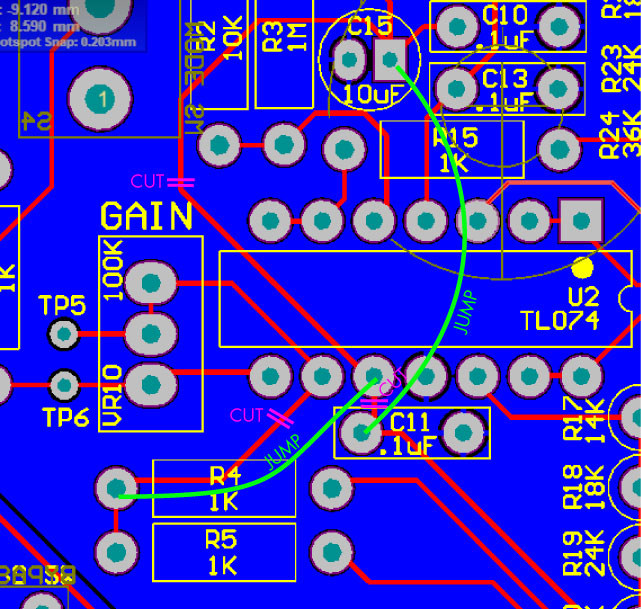
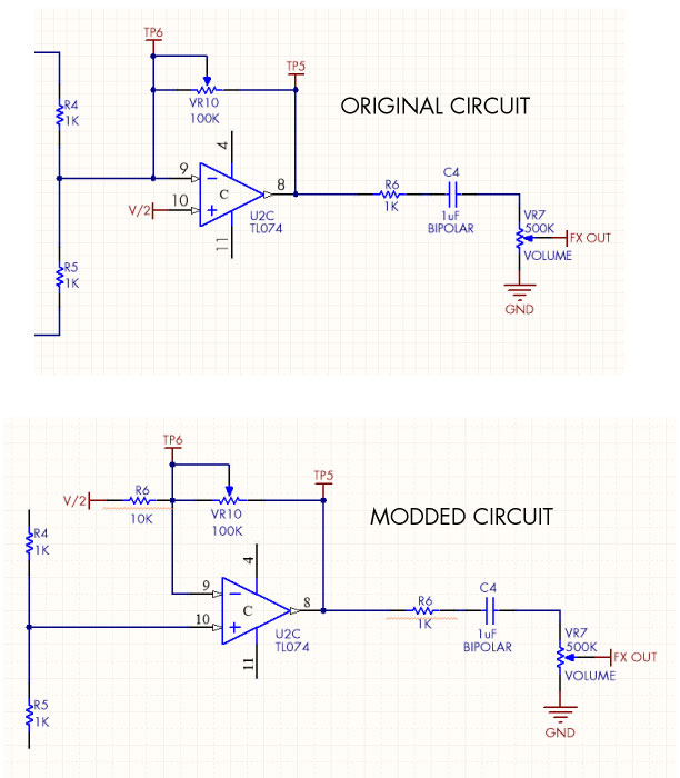
From looking at the schematic in the assembly manual, you can see 2 noninverting opamp stages and one non-inverting…resulting in an inverted output….so you are correct. If you want to mod your Quaverato, you can turn that last inverting opamp stage into a non-inverting stage by cutting 3 traces, running 2 jumper wires, and adding 1 resistor (10K ohm, or so). The first picture shows the traces that you need to cut (in purple) and the jumper wires you need to run (in green). The second picture shows where to solder the resistor (sorry for the horrible artwork)…soldered to pin 9 from the V/2 rail.
Let me know if you have any questions.https://zeppelindesignlabs.com/wp-content/uploads/2024/05/noninverting-quaverato.jpg
https://zeppelindesignlabs.com/wp-content/uploads/2024/05/noninverting-quaverato-2.png
https://zeppelindesignlabs.com/wp-content/uploads/2024/05/ORIGINAL-MODDED-circuit.jpgParticipantThat’s so kind to provide that solution Brach, thanks. Do you know this mod would have any other knock-on effects?….alter the sound or functionality in any way?
Thanks
Ben
ParticipantBen,
I’ve never done this mod, but theoretically it shouldn’t alter the sound. The gain will be different, so you’ll have to adjust the gain trim pot again by ear. But it shouldn’t affect the bandwidth or frequency response. The signal through the optocouplers will be going into a higher impedance (less load), so the response of the LDRs may be slightly different, which you could adjust with the tone trim pots.
-BrachParticipantHi Brach, thanks again for the comprehensive pics etc, very helpful. So I’ve cut the traces fine, and am just about to do the jumpers, the one from R4 to the pin on U2-TL074 is fine, but the one from C11 to C15 is a little more tricky, access to that solder joint on C15 is quite restricted by the cap itself on the component side of the board and by the ‘Harmonic Mix’ pot on the other side, I’d prefer if possible not to unsolder the pot. So I’m wondering if it’d be possible to run that jumper from C11 to C10 instead as there’s a direct trace between the required lead on C15 to C10 and that solder joint is far easier to reach. Electronically I can’t think why this wouldn’t work but I wanted to check, I may be misunderstanding it.
Many thanks
Ben
ParticipantYes, you can run that jumper from C11 to C10, it’s all the same node. But I was expecting you to run these jumpers on the solder side of the board. Use very fine wire (i use 30 gauge), which you can acquire from the inside of old vga cables or something similar. These traces should be run close to the circuit board surface. You should just bend up the mix pot and solder the wire to the correct pad and then bend the pot back down on top of the wire and insulation paper. But to answer your question, you can run the jumper from anywhere on that node.
The resistor should also be placed on the solder side of the board.Tuhrup
ParticipantLet me know if you have any questions.
-
AuthorPosts
Viewing 7 posts - 1 through 7 (of 7 total)