- Your cart is empty
- Continue Shopping
Home › Forums › VPM-1 Forum › VPM-1 FAQ & Support › VPM-1 Unbalanced Estero
Tagged: VPM Stereo problems
- This topic has 6 replies, 3 voices, and was last updated 3 years, 4 months ago by
brach.
Viewing 7 posts - 1 through 7 (of 7 total)
-
AuthorPosts
-
chenao72
ParticipantHi,
I recently bought an VPM-1 kit with the stereo upgrade kit and the expression upgrade kit. I finished putting it all together last week following the instructions to the letter. Finally, I completed the Stereo calibration and the final pedal calibration without any problem.
Wile testing the stereo configuration (dip switches 1 and 5 on the main board were turned ON), I noticed the channels seem unbalanced.
I conducted all the testing using the linear tapper, and the stereo cables provided with the stereo upgrade kit:
1) Plugging my guitar into the VPM black input: If I then plug the VPM black output into my amp, it gives me significantly more volume than when I plug the VPM red output into my amp.
conversely
2) Plugging my guitar into the VPM red input: If I then plug the VPM red output into my amp, it gives me significantly more volume than when I plug the VPM black output into my amp.
Things I have tried (unsuccessfully):
– Checked voltage levels on the main board and all are OK, and the tunnel jack has audio signal.
– Used dark thick nail polish to seal the ends of all 4 octocouplers.
– Repeated Stereo calibration process and pedal calibration twice already.
– Tested the optocouplers: Using the diode test function in my multimeter I measured LED bias, while at the same time, measuring the resistance of the LDR using a different multimeter. The idea was to have the LEDs activated with the bias test to have some light and check the LDRs at the same time. Keep in mind all these measurements were done on the components in the circuit (i.e. I didn’t desolder anything). The results for LED bias (red probe on square pad and black on circular one) and resistance are as follows:Opto 1A: 1.900 V. ; 0.073 MegaOhms
Opto 2A: 1.894 V. ; 0.127 MegaOhms
Opto 1B: 1.842 V. ; 0.232 MegaOhms
Opto 2B: 1.846 V. ; 0.130 MegaOhmsI am 100% sure the LDRs were used correctly. I followed the Opto building instructions to the letter, building and immediatlly installing one pair at the time, marking the optos with the dotted LDRs and installing them in position 1 on the main and stereo boards.
Any help will be most appreciated.
Regards,
Carlos.
brach
ParticipantCarlos,
Sorry for your stereo trouble.
First of all let me ask, when your VPM-1 kit came in the mail it should have had 2 pairs of LDRs in the stereo kit bag…did it also have one extra pair in the VPM-1 main kit? If so, which 2 of the 3 pairs did you use? We accidentally sent out 3 pairs of LDRs a few times, which can be confusing.
Second, did you make sure to change all 7 jumpers when running the stereo setup routine?
Third, it would help if I can see a picture of the plastic zip lock bags that the stereo LDRs came in. It would help for me to see how the numbers were written on the bags to know what generation of test LDRs were sorted. Could you please send me a photo of them to this address?:
info “at” zeppelindesignlabs “dot” com
Forth, it might be good to add some sticky tack (poster putty) on the ends of the optocouplers just to ensure they are really sealed. Sometimes if the holes are too big nail polish won’t seal them. Make sure you run the stereo setup routine again after you do that.
-BrachGuestHi Brach,
Thanks you very much for your prompt reply. Here is the info you requested:
1) The stereo kit I recieved contained 2 pairs of LDRs, and the main Kit came with none.
2) All 7 jumpers (Cal-1… Cal-7) were installed when running the stereo routine (both times I ran it), and once the routine was done I pull them out and put Jumpers J5 and J6 back in place.
3) I am sorry, but I do not have the bags the LDRs came in. They went into the trash last week. What I can tell you is that there were 2 small bags, each containing one pair of LDRs, each pair consisting of a marked LDR and a non-marked one. These bags came as part of the stereo kit, stapled to one another.
4) I could try the poster putty, but I think the optocouplers are well sealed, as I used thick nail polish and built the seal using several layers to completely fill any gap. Additionally, when I was measuring the LDRs while having the LEDs powered at bias voltage, I tried measuring the resistance with my workbench spotlight on and off and I didn’t detect any difference in the measures. I will send you pictures of the optocoupler ends so you can see and let me know if you still think the seal is not what it should.
An additional question for you. If I were to replace the optocouplers using commercially available ones, would any of these models from Advanced Photonics work? :
* NSL-32
* NSL-32SR2
* NSL-32SR2S
* NSL-32SR3I have about 10 of each and I can send you the satasheets for you to take a look.
How would one go about making pairs for each channel? what would the tolerance be?
Thanks again for your help.
Carlos H.
ParticipantHi Brach,
Thanks you very much for your prompt reply. Here is the info you requested:
1) The stereo kit I recieved contained 2 pairs of LDRs, and the main Kit came with none.
2) All 7 jumpers (Cal-1… Cal-7) were installed when running the stereo routine (both times I ran it), and once the routine was done I pull them out and put Jumpers J5 and J6 back in place.
3) I am sorry, but I do not have the bags the LDRs came in. They went into the trash last week. What I can tell you is that there were 2 small bags, each containing one pair of LDRs, each pair consisting of a marked LDR and a non-marked one. These bags came as part of the stereo kit, stapled to one another.
4) I could try the poster putty, but I think the optocouplers are well sealed, as I used thick nail polish and built the seal using several layers to completely fill any gap. Additionally, when I was measuring the LDRs while having the LEDs powered at bias voltage, I tried measuring the resistance with my workbench spotlight on and off and I didn’t detect any difference in the measures. I will send you pictures of the optocoupler ends so you can see and let me know if you still think the seal is not what it should.
An additional question for you. If I were to replace the optocouplers using commercially available ones, would any of these models from Advanced Photonics work? :
* NSL-32
* NSL-32SR2
* NSL-32SR2S
* NSL-32SR3I have about 10 of each and I can send you the satasheets for you to take a look.
How would one go about making pairs for each channel? what would the tolerance be?
Thanks again for your help.
Carlos H.
ParticipantCarlos,
Thank you very much for the clear and detailed information. It is very easy to work with you in troubleshooting your pedal. I wish all our customers could communicate as well as you.
That’s no problem about the bags being thrown away. The numbers on the bags might have been helpful to me but it’s not necessary.
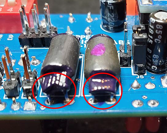
Thank you for the photos you emailed me. The optocouplers look mostly good, but there was one angle that kind of looked like they may need some more sealant. Here’s the edited photo…
https://zeppelindesignlabs.com/wp-content/uploads/2023/01/20230128_145356.png
…but if you tested them with your spotlight and they didn’t change resistance then they are probably sealed…but it would be good to be extra cautious in this matter just to rule out all the variables we can.
When I was designing the VPM-1 I looked into using the NSL-32 optocoupler, but it was hard to get consistent result from them…at least from the batch that I was testing. I ended up spending a couple of months developing my own rigorous test procedure for LDRs that we purchase in bulk. It ended up being way more reliable and economical for us to sort our own LDRs. But in looking at the datasheet for the NSL32SR2 (sorted) variety, they should be matched enough to work with the stereo VPM-1 (any type A-G). That’s assuming the datasheet is correct. I’ve often had a hard time getting the promised results from LDR datasheets in real-life situations. But if you have the sorted variety you can give them a try. It shouldn’t matter which optocoupler goes in which location, if they really do have those specs.
Good luck!
-BrachParticipantHi Brach,
Thanks for your repply. I am glad my relatively lengthy descriptions help. It comes natural as my background is in engineering, but not in electrical engineering, mind you. So it happens that I started playing guitar late in life, as a hobbie, and now I am exploring pedal assembling and starting to read about pedal electronics and modification.
Since I have several SNL-32SR2A, I will find 4 of the most similar in the batch and give them a try. To simplify trying different optocouplers, I will remove the ones currently installed in the PCBs (main and stereo) and install sockets in their place.
Any thoughts or suggestions will be most welcomed.
Regards,
Carlos.
ParticipantIt’s great to meet another engineer! That’s why I like your communication style!
Sockets might be nice to have, but I have found them to be unreliable if you are going to be gigging or traveling much with this pedal. But if you really want them then make sure you get the kind that can accommodate short component legs…because the optocouplers that you made now have short legs after you cut them off during assembly. That’s really the only suggestions I have other than use caution when removing the components from the board. They are delicate and the traces and pads on PCB are somewhat delicate too.
Good luck!
-Brach -
AuthorPosts
Viewing 7 posts - 1 through 7 (of 7 total)