Forum Replies Created
-
AuthorPosts
-
 brachModerator
It’s no problem. I like helping people get their products working right.
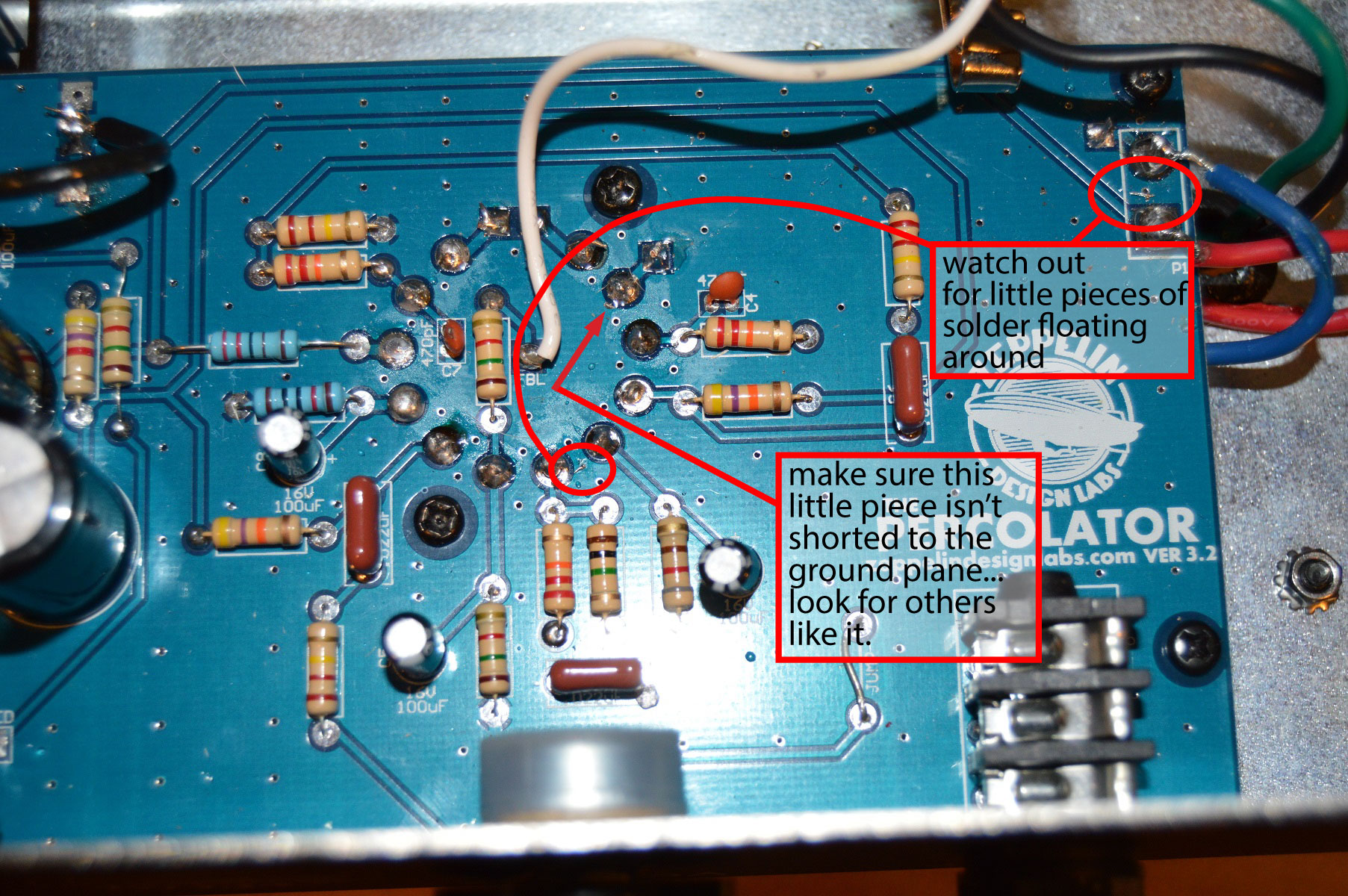
Here’s another edited photo that you sent me earlier…just to illustrate these points…
If it’s sparking, the sparks have to be going somewhere…usually a black spot on the board. Can you find out where they are going? It would helpful if you could try to take a couple more close up pics of R15, both sides of the board. Maybe i could see something.
The via isn’t a soldering point, just a tiny hole through the pcb with no blue solder mask on top of it, so they are easy to accidentally bridge solder to if it overhangs the pad much.
-BrachbrachModeratorTo answer your questions from earlier…
It might not be destroyed…resistors are often more resilient that we think. Measure it and see if it’s still close to 220 ohms. It’s a 220 ohm, 1/2W, 1% tolerance metal film resistor…but you can use any tolerance and type of resistor, as long as it’s 220 ohms and at least 1/2W.
-BrachbrachModeratorIt’s never good when the resistors glow. It means there is too much current going though it. How is it sparking? My guess is that it’s glowing because it’s sparking and not drawing current elsewhere. Does it still spark with the tube removed? Sparking is an indication that it’s shorted (to ground) somewhere, possibly the via between C10, C9, and one of the pads of R15. Make sure you only have enough solder on the resistor pads that you need, and it’s not spilling over to the copper ground plane (or vias) around the pads. It might help to use some electronics flux (not plumbers flux) to clean up your solder joints if necessary. If you can’t see anything obvious from the top side of the board, then you’ll have to take it out and look for shorts on the solder side. Look for black burn marks on the PCB where it was sparking as an indication of where the shot is. Try to refrain from turning it on until you think you’ve found and fixed the problem, otherwise you might blow the fuse.
Good luck.
Let me know what you find.
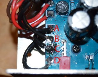
-BrachbrachModeratorThanks for pictures. I edited one of them for reference here…
You say that you have ~120VAC across pads A and B.
Are you getting no voltage across pads C and D?…I’m assuming you get no voltage.
Please test the AC voltage across pads A and D…you should have ~120V with the power switch on, is this correct?
Assuming you don’t have voltage across C and D, the trace from pad C to B must be broken.
With the IEC power cable unplugged and power switch off test for continuity between C and B. They should be connected, but if they are not then the trace is broken. If this is the problem then you need to jump those 2 pads together with some thick wire…use about 1/4″ of the extra transformer wire that you cut off…tin it first and remove the insulation.Upon closer look at the photo, please add a little more solder to pad B and re-flow that joint. Make sure the wire is making good connection to the pad. Do this first, to make sure that is not the problem.
Keep me posted.
Good luck.
-BrachbrachModeratorThanks. I’ll be looking for the pictures.
Are you getting 120ish volts at the board, though (not at the jack)? I just want to be sure the problem is at the transformer input, not another place on the board.
-BrachbrachModeratorThat makes since. It seems that the power transformer isn’t getting any voltage…probably because of the damaged pad. Would it be possible to send me some photos of the board where the pad got damaged? If you can’t attach them to the forum post then email them to me…brach “at” zeppelindesignlabs “dot” com
Just to make sure…are you getting ~120vac at P5 (where the wires come in from the IEC jack)?
Thanks.
We’ll get this fixed.
-BrachbrachModeratorIf the trace from that pad broke then that would explain why you are not getting any voltage on most of the test points. See if you can make that repair and let me know the results. If you want any help or tips on that process let me know.
Good luck.
-BrachbrachModeratorHi Grant,
This Brach, the electrical designer here at ZDL.
I’m curious what voltage reading you are getting from your power transformer. What AC voltage do you get across the brown wires coming from the power transformer (not from ground, but across the wires)? What AC voltage do you get across the Red wires? What DC voltage do you get at testpont 1 (from ground)?…If you get nothing, are the bridge rectifiers (BR1, BR2) in the correct orientation?
Thanks.
-BrachbrachModeratorThe good thing is, the amp works…it’s got the correct voltages in the correct spots. The problem is some of the signal isn’t making it through somehow to the output. If I understand you correctly, every time you re-flow/re-solder some stuff on the board the amp gets louder. To me, that’s a sign that there’s some sort of connection issue…most likely it’s something that’s not making a good connection somewhere (as opposed to a short)….only letting a bit of the signal through. If you are at all un-confident about the solder joints then please check them again…look very closely at each joint. I know it’s a pain, but that seems to be what all signs are pointing toward.
Just checking, you are using an 8 ohm speaker, correct?
If all the tube voltages are correct then the tube is working correctly. Besides that, we test every tube before we send it out, so there’s very little chance that it’s a tube problem. Vacuum tubes contain a bunch of tiny parts, very close together, so often times they do rattle when they are shaken vigorously…unless you are talking about loose parts in the tube, but if that’s the case then it most likely wouldn’t have the correct voltages on the tube pins because something wouldn’t be making a connection in the tube.
Thanks for verifying that you tightened the tube socket pins. If you are pretty sure all the tube pins are making good connection then you don’t have to keep trying to tighten them. I just know in the past these symptoms have been caused by that.
You’ve probably already done this, but I wouldn’t hurt to double check the values of resistors in the signal path to make sure they are correct.
Please keep me posted with how things are going.
-BrachbrachModeratorThe fact that re-flowing the resistors from the top side changed something, tells me that you had another bad solder joint somewhere. Since your Percolator still isn’t working properly it makes me think that there is another bad solder joint somewhere. You may be at the point of taking the board out of the chassis again and reflowing all the joints and double checking for solder bridges (shorts).
Have you tightened the tube socket yet? If so, did you tighten the socket and re-flow the solder joints in the same step, or did you test the amp between each of those steps? I’m just wondering if it might have been fixed when you tightened the tube socket, but you didn’t notice it. If that might have been the issue or part of it then gently re-tighten the socket again…if that works it will keep you from having to remove the board from the chassis. When tightening the sockets focus on pins 3, 6, and 11 (next to R1, R6, and R11)…these are the grid pins. The “grid” is where the signal comes into the tube stage. If you have correct voltages on the other pins then it’s most likely that the signal is not making good connection to one of these pins…if it’s the tube socket at all.
I don’t know if you have one, but it really helps to get one of those solder sucker tools to remove the solder from the holes after you remove the wires. They are very helpful in putting the board back after you remove it and removing excess solder from around the pads if you have any big solder globs anywhere.
We are really close. Keep persevering!
Good luck and keep in touch.
-BrachbrachModeratorHyllej,
The fact that all the tube voltages are correct is a good sign that the tube circuitry is functioning properly. The first thing to do is to tighten the tube socket. To do this you just need to get some sort of sharp, pointy tool and gently pry the tube socket contacts closer together to help them grip the tube pins better. Sometimes they get spread a little to far apart in the “loosening the tube socket” step, and they don’t make good contact with the tube pins.
If this doesn’t work then you probably need to re-flow (re-solder) the solder joints again. I know it’s a pain, but the fact that you had one bad solder joint is a sign that other’s could be bad as well. At first, just re-flow the resistors from the top (component side) of the board so you don’t have to take out the PCB. If that doesn’t work then you’ll have to take out the board and check really closely for solder bridges (shorts) and re-flow the capacitors and other components that you weren’t able to get to from the top of the board.
You really shouldn’t turn on your amp without a load (speaker) attached. It’s really bad for the tube. So make sure the speaker is plugged in when you test it. It’s not uncommon for properly working tube amps to behave like that when they don’t have the speaker plugged in…so i’m not worried about the buzzing with no load. The problem is that the signal is not making it through somehow. We’ll get it sorted out one way or another.
-BrachbrachModeratorMake sure that the feedback wire is connected to the correct lug of the output jack. If it’s connected to the ground lug instead of the positive lug of the output jack then it would exhibit symptoms like those. Let me know what you find.
Good luck,
-BrachbrachModeratorTroy,
I’m sorry the display is giving you trouble.
I agree with you that it does seem like there is no issue with the display itself. My guess is that some pins are not making good contact with the header pins. I often have to bend the display leads pretty far to get them working properly. Are any segments working on all three digits, or are only pieces of 1 or 2 digits working? Also, are the same segments not working on each digit? If we know which segment or digit is not working then we can tell which pins are not making contact.
Let me know.
Good luck!
-BrachbrachModeratorThat’s really cool! Please keep us informed with how it works in your installation.
Good luck.
-BrachbrachModeratorThat supports my theory. By setting the bias that high, you are increasing the load on the SMPS, allowing it to stabilize. You now have 1mA going through each FET, which is fine, as long as you are ok with the sensitivity of the Cortado at that bias setting. If you need to adjust the bias back down (for sensitivity reasons) then just do as i mentioned in the previous post and plug in a different condenser mic into another channel on the converter to add a higher load to the phantom power SMPS at the same time the Cortado is plugged in to the first channel.
Let me know if you have any more questions.
-Brach -
AuthorPosts