- Your cart is empty
- Continue Shopping
Forum Replies Created
-
AuthorPosts
-
brach
ParticipantFanyo,
Thanks for the detailed info. I don’t feel defensive about my design work or the Quaverato. I’m constantly learning and I would probably even design the Quaverato somewhat differently if I was to do it over again these days (after all I’ve learned in the years since I designed it). I’m always wanting to learn and be a better engineer, so thanks for letting me be a part of this troubleshooting process.
One thing that I’m curious about is to remove the looper from the equation…have you tried using the Quaverato and other pedals together outside of the looper? According to the user manual the PXL live does have “buffered bypass.”
I know you said you tried every conceivable combination of pedal orders and it happened on all of them…but If the Quaverato is the very last pedal in the chain (hooked up to the looper) before the amp, does it still cause this issue? What about if it is the last pedal in the chain after the looper, where the looper output is plugged in to the Quaverato input and the Quaverato output is going into the amp, does the volume jump happen then, when other pedals are turned on?
Have you tested the Quaverato when it is just plugged into the amp and your guitar? I’m curious if the boost you hear is really the normal volume level of the Quaverato, and the volume level is being reduced when it is in the pedal chain.
So far, from the list of facts you gave, none of them disprove my original hypothesis of it being a frequency sensitivity issue. I don’t know how you can say this is definitely not true. This type of thing can be experienced with an overdrive or distortion pedal that has the tone know all the way up…there is often a large boost associated with that adjustment, most of the time at least 20% boost. Most of the time, when modulation effects have this issue it is at a much lower volume level than what you are experiencing here, but it doesn’t always have to be. The same principles could be at work here. Unfortunately, it will take more than a multimeter to test it…you would need at least an oscilloscope and signal generator. You could experiment with the crossover switches, changing the frequency to see if that has an impact on the boosted/jumped signal. If it does, that’s a clue pointing to what is happening.
Let me know what you find when you have the opportunity to check these things out.
Good luck!
-BrachParticipantMatt,
Thank you for the video. I hear what you are talking about.
The volume not cutting out all the way tells me that you have a lot of gain after the volume pedal. On the VPM-1 the volume is guaranteed to get reduced to something like -70dB or so (I can’t remember the exact specs). So the signal is never completely gone, but just reduced by a whole lot. This is the way all volume pedals work, even the EB Jr, but in the case of passive pedals the volume is reduced much more, because it gets really, really close to ground level…so it would take tons of gain to make it audible again. With active volume pedals, depending on the volume reduction technology, the volume can only be reduced a finite amount. So in this case, the reduced signal is getting boosted back up again by the following pedals and amps in the chain. We mention in the manual to only use as much gain on or after the pedal as necessary. Unfortunately, because of the gain structure of this pedal, it’s not an exact drop-in replacement for the passive EB pedals…some signal chain gain adjustments may need to be made for it to operate optimally. It’s one of the limitations of the particular technology, I’m sorry about that.
After hearing it, I think the distortion sound is caused by what I was speculating in my previous post. This happens on the very first of the 256 volume level steps. This happens on all VPM-1s but most of the time it’s inaudible because the gain structure is lower. I think a possible mod to help it be less audible is to add a small value capacitor across the LEDs of the optocouplers. I’ll try to look into this when I get a free moment. But I’m sorry for the annoyance and trouble with these issues.
-BrachParticipantFanyo,
I have never heard of this issue before. There is nothing uncommon about the input or output impedance of this version of the Quaverato, so that’s not the issue. My only guess is that it has something to do with the frequency response of the Quaverato. If you have drives or other pedals that are sensitive to the frequency response of the input signal, they may be boosting those particular frequencies more than others. Have you tried changing the order of the pedals in your chain? Most people run modulation effects like the Quaverato toward the end of the pedal chain, partially for this reason…modulation effects often have a tendency to shift the phase of different frequencies. Another thing that might help is to keep a non-true bypass pedal directly after the Quaverato…like a tuner pedal or a buffer pedal or something.
I’m sorry about this issue. I hope you can find a solution that works for you. I’m sorry that I can’t be of more help.
Take care.
-BrachParticipantFanyo,
I think your issue may be a different than Tyler. If you are experiencing a “dip” in volume as you move the treadle, that is caused by the volume level table in the microcontroller not being populated correctly. If you run the stereo setup routine, that will re-populate the table and is likely to fix it.
To directly answer your questions, my suggestion about adding a capacitor was only theoretical. I have never tried it myself. It will take some experimentation to find the exact capacitor because I can’t remember the exact frequency of the PWM, but I think it’s around 30kHz.
-BrachParticipantTyler,
Thanks for the serial. Yes, we did build that one with the expression mod.
In dealing with 8 bit control, there are only 256 discrete steps of brightness on the LED (controlling the LDR). We’ve done some processing magic to acquire a few more steps toward the bottom of that range…which, I believe is what is causing the frying or distorted sound, as the final step flickers on and off. I don’t remember experiencing this before, but that is what I think is happening. Theoretically this distortion is at the lowest possible volume level of the pedal (without being turned all the way off). So this artifact should be rather quiet, but if there is a lot of gain added to the signal after the volume pedal then this sound will get boosted more into the audible range. One thing you can do is to change gain structure of your pedal board/amp set up. Keep the gain on the pedal only as high as necessary. Also keep the gain as low as possible after the pedal or change the location of the pedal in your signal path. If you are going straight into your audio interface, be mindful of keeping the gain low on that signal path too (be very careful when using compressors). Doing this will also help with the long turn off time you are experiencing.
If that doesn’t help or is not practical to do, then you might be able to mod the circuit hardware to help smooth out this fast switching of the LED. If you add a very small capacitor between the LED pins (on the both optocouplers) then that should delay the turn on time so that this artifact is less audible. This cap should be very small. I can’t remember off the top of my head what frequency the PWM controlling the LEDs is, so I can’t say what value of cap might work…but you can experiment by trying a variety of capacitors in the range of 100pF to around 5nF. Maybe start with the larger values and work down to see if that noticeably changes anything.
I’m going to be out of town for the next week so I probably won’t be able to respond right away, if you have any questions.
Good luck.
-BrachParticipantThat’s not the correct serial, can you double check that again?
Thanks.
-BrachParticipantTyler,
I’m sorry that you are experiencing this trouble. I have some questions for you…
I’m assuming that you built your VPM-1 from a kit…is this correct?
Has it ever worked correctly, in that the volume quickly decays instead of slowly fading out in the heal down position?
What is your pedal’s serial number?
-BrachMay 23, 2024 at 2:15 pm in reply to: VOX Repeat Percussion: how close can the Quaverato come? #42218ParticipantThat is true, you have to have a midi controller to recall the presets on the Quaverato. Good luck with the kit. Thanks again for your interest!
-BrachMay 23, 2024 at 11:23 am in reply to: VOX Repeat Percussion: how close can the Quaverato come? #42216ParticipantCnpcnp,
Thanks for your interest in the Quaverato.
I’m not an expert with the Vox repeat percussion effect, but from what I’ve heard (from demos on youtube) the Quaverato should be able to get pretty close to it. As with any very old piece of gear, and especially cheaply made gear like the repeat percussion (and all guitar effects from that era), you will find a good amount of variation with how each unit sounds. This is because of the high tolerance components and large variation in transistor characteristics from that era…not to mention component values drifting over the years. From my experience, each piece of vintage gear has its own unique tonal characteristics and “sound” compared to other units of the same model, from the same era. So, if you are trying to match a particular repeat percussion unit, I can’t say if the Quaverato will have the same exact tonal characteristics, but it can definitely get very close to the type of sound the designers of the repeat percussion were trying to achieve.
That’s just some thoughts…
Take care.
-BrachParticipantYes, you can run that jumper from C11 to C10, it’s all the same node. But I was expecting you to run these jumpers on the solder side of the board. Use very fine wire (i use 30 gauge), which you can acquire from the inside of old vga cables or something similar. These traces should be run close to the circuit board surface. You should just bend up the mix pot and solder the wire to the correct pad and then bend the pot back down on top of the wire and insulation paper. But to answer your question, you can run the jumper from anywhere on that node.
The resistor should also be placed on the solder side of the board.ParticipantJason,
I wrote the troubleshooting guide to be followed from step 1 onward. …as a flow chart of sorts as you answer the questions. It’s probably not the best course of action for troubleshooting, but it’s a starting point. So based on your symptoms, hopefully there is a point in the guide that will deal with that problem. The voltage chart is for reference as the troubleshooting guide directs you to measure certain points on the board.
Let me know if you have questions.
-BrachParticipantBen,
I’ve never done this mod, but theoretically it shouldn’t alter the sound. The gain will be different, so you’ll have to adjust the gain trim pot again by ear. But it shouldn’t affect the bandwidth or frequency response. The signal through the optocouplers will be going into a higher impedance (less load), so the response of the LDRs may be slightly different, which you could adjust with the tone trim pots.
-BrachParticipantBen,
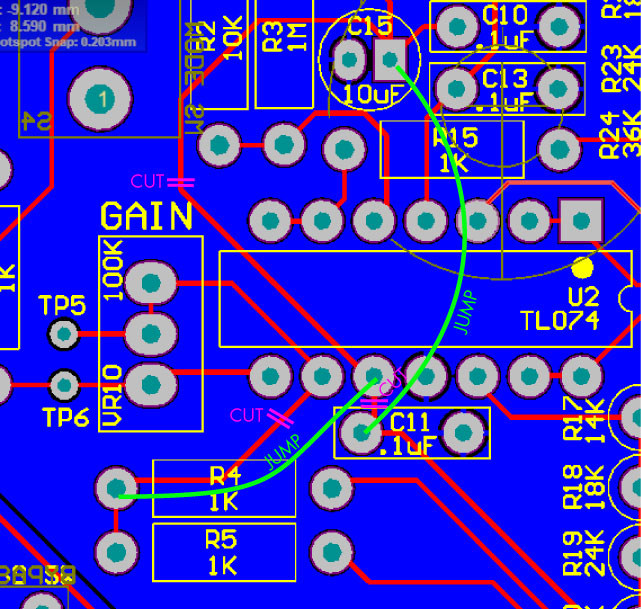
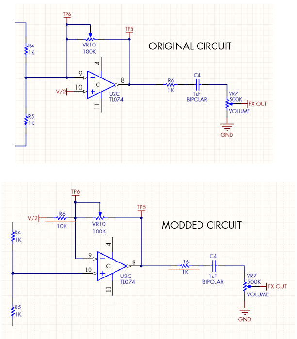
From looking at the schematic in the assembly manual, you can see 2 noninverting opamp stages and one non-inverting…resulting in an inverted output….so you are correct. If you want to mod your Quaverato, you can turn that last inverting opamp stage into a non-inverting stage by cutting 3 traces, running 2 jumper wires, and adding 1 resistor (10K ohm, or so). The first picture shows the traces that you need to cut (in purple) and the jumper wires you need to run (in green). The second picture shows where to solder the resistor (sorry for the horrible artwork)…soldered to pin 9 from the V/2 rail.
Let me know if you have any questions.https://zeppelindesignlabs.com/wp-content/uploads/2024/05/noninverting-quaverato.jpg
https://zeppelindesignlabs.com/wp-content/uploads/2024/05/noninverting-quaverato-2.png
https://zeppelindesignlabs.com/wp-content/uploads/2024/05/ORIGINAL-MODDED-circuit.jpgParticipantBenjamino1979,
Email me and I can give you the latest Arduino code package…info “at” zeppelindesignlabs “dot” com
-BrachParticipantNeil,
I’m sorry about this trouble.
I’m not sure what is happening here. Does the frying sound happen when the treadle is stationary, or just when it is moving through the lowest part of its action? There are some interesting things that are happening at the very lowest volume setting that may be causing some sonic artifacts. I’ve never heard of this happening, but I suppose it’s possible.
A question that follows is how much gain are you using on the VPM-1 or after it? If you use a lot of gain, then some of the normally inaudible artifacts might be more audible if the volume is turned up enough.
Also, it may help to re-set the volume level table in your pedal’s software by running the “stereo setup routine” discussed in step E-3 of the troubleshooting guide (if you haven’t done this already).
I hope this is helpful.
-Brach -
AuthorPosts