- Your cart is empty
- Continue Shopping
Forum Replies Created
-
AuthorPosts
-
brach
ParticipantThank you so much!
I’m really looking forward to playing with these things. The links you provided are really getting me inspired to start designing some new things with piezo film. I’ll make sure to use a heat sink when soldering them. Thanks for the heads up. Please keep us posted with how these work in your application of drum mics with the Cortado. I fear they may have too much gain, but there are ways around that.
Thanks again and good luck!
-BrachParticipantWow! Certianally! Thank you very much for the offer.
Our address is:
Brach Siemens
Zeppelin Design Labs
2950 N. Western
Chicago, IL
60618I’ll play with them and see what I can figure out. I’m noticing the datasheet has some interesting information presented as experiments that the manufacturer has done. What devices do you harvest these things out of?
Thanks again!ParticipantRussek,
I actually haven’t tried that, but theoretically it should work. One thing to be mindful of is that often time PVDF piezo sensors are is more sensitive than PTZ piezo sensors, depending on the application. So you may have to reduce the incoming voltage via a voltage divider to account for the possible higher voltage input to the Cortado.
Now that you’ve got me thinking, I’m going to get some film piezo sensors and do some experiments when I get the chance. Thanks for bring it up.
Good luck.
-BrachParticipantYes it does need a case ground, but the circuit is grounded to the inside of the chassis…so it would be fine to paint the outside of the chassis.
I’d love to see it when it’s painted…if you feel like posting picture.
Good luck.
-BrachParticipantYes, the resistance across the test points connected to the high and low trim pots will change after you solder the jumpers. The Hi and low trim pots need to be measured and set while the jumpers are not soldered together. If you try to measure them while the jumpers are soldered the bias voltage from the opamp will skew the resistance measurement on your meter. You can always adjust them while the jumpers are soldered by listening to your guitar tone and making adjustments accordingly, but if you want to use your meter to set them you’ll have to remove the solder jumpers first.
Thanks for asking.
-BrachParticipantSorry it took me so long to respond to your post…
I’m sorry to hear about the XLR jack problem. I’ve experienced that once before and I ended up using a different XLR cable and it seemed to solve the problem. I wasn’t able to figure out what was the issue. Now that i’m thinking about it, I’m wondering if the plastic piece that holds the pins was in crooked or out of alignment somehow, but it seems that you’ve tried that already. Does the metal XLR male housing with out the plastic pin holder inside it fit on one of your XLR female cables alright? That might give a clue if the housing or the pins are the problem.ParticipantHave you re-flowed all the joints on Q1 (and the rest of the board for good measure)? Are pins 2 and 3 shorted?…what’s the resistance across them? If R1 is measuring 3.3M ohms, then it seems like pins 2 and 3 are shorted…either by a solder short or internally. If it seems like it’s an internal short then remove Q1 from the pcb and measure across pins 2 and 3 with an ohm meter. From my experience, this type of problem is usually an assembly issue.
Keep me posted.
Good luck.
-BrachParticipantIf pin 2 of Q1 is at 44V then pin 2 of Q2 should also be at 44V…if not then Q2 isn’t making good connection to the circuit, which could cause these symptoms. You might want to re-flow your intern’s solder joints for good measure.
Note the voltages on the picture in this post:
Are there any other voltages that aren’t matching up to the voltages on this picture?
Good luck. Let me know.
-BrachParticipantExcellent!
ParticipantLloyd,
That”s great to hear that everything is working well for you. Let me know if you have any more questions.
Good luck!
-BrachParticipantMost metal film resistors (usually blue in color) are specified to be within 1% tolerance of the given value. This is indicated by the brown stripe at the end of the colored bands. If you are using carbon film resistors (usually tan in color), they are usually 5% tolerance, indicated by the gold stripe at the end of the colored bands. If all you have is 5% resistors then you could hand match them. In practicality it’s really not that big of deal with the Cortado in your application. The weakest link in the chain by far will be how well you couple the disc to the floor boards. The audio fidelity of the system mostly hinges on that.
Good luck.
-BrachParticipantHi Lloyd,
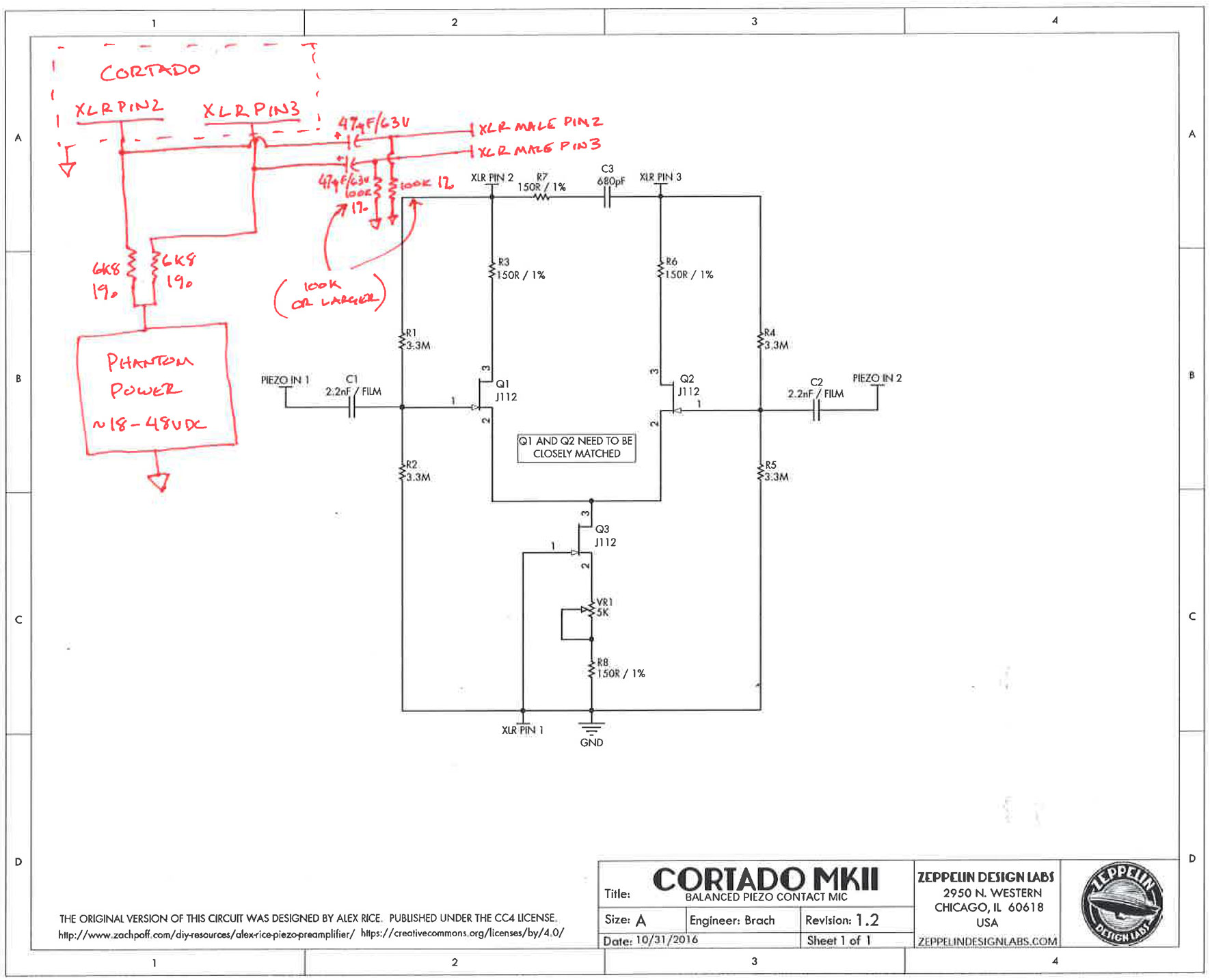
Attached is a circuit that I just drew up. It shows you how you could use your external power supply as phantom power for the Cortado. As you can see, pins 2 and 3 of the XLR jack are used for both signal and phantom power. The signal (an ac voltage) is superimposed on the DC phantom power. The signal is the separated from the DC via the two 47uF/63V capacitors. Make sure they are rated for a voltage higher than your phantom power. The XLR pins (2 and 3) are separated from each other via the two 6.8K resistors. The two 100K resistors are to give the caps a place to drain when nothing is plugged into the XLR cable. You may need to increase the value of these (to has high as 1M) if the Cortado has a hard time driving the signal past them (ie the output signal is lower than you want). Let me know if you need more explanation or if you have other questions.
Good luck.
-Brach
 Participant
It’s no problem. I like helping people get their products working right.
Here’s another edited photo that you sent me earlier…just to illustrate these points…
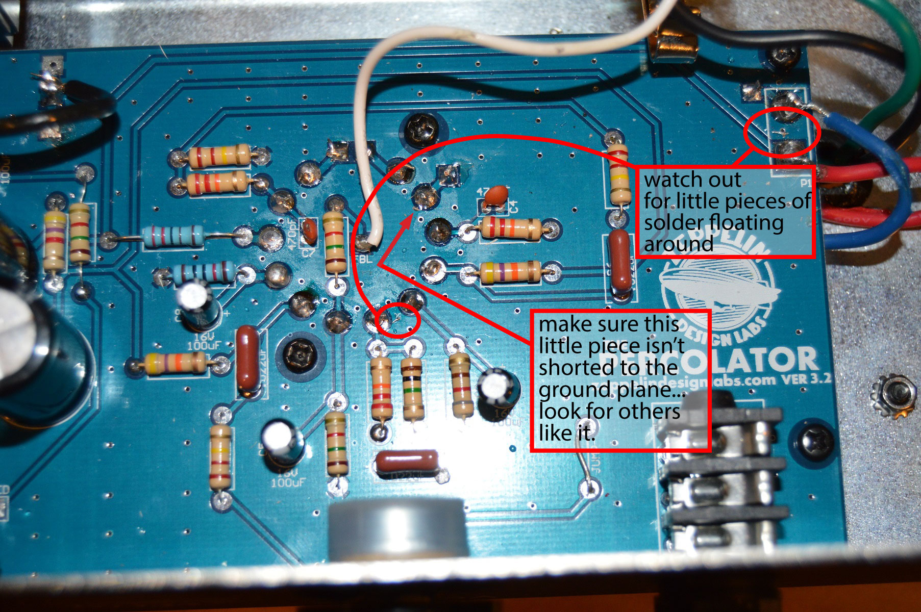
If it’s sparking, the sparks have to be going somewhere…usually a black spot on the board. Can you find out where they are going? It would helpful if you could try to take a couple more close up pics of R15, both sides of the board. Maybe i could see something.
The via isn’t a soldering point, just a tiny hole through the pcb with no blue solder mask on top of it, so they are easy to accidentally bridge solder to if it overhangs the pad much.
-BrachParticipantTo answer your questions from earlier…
It might not be destroyed…resistors are often more resilient that we think. Measure it and see if it’s still close to 220 ohms. It’s a 220 ohm, 1/2W, 1% tolerance metal film resistor…but you can use any tolerance and type of resistor, as long as it’s 220 ohms and at least 1/2W.
-BrachParticipantIt’s never good when the resistors glow. It means there is too much current going though it. How is it sparking? My guess is that it’s glowing because it’s sparking and not drawing current elsewhere. Does it still spark with the tube removed? Sparking is an indication that it’s shorted (to ground) somewhere, possibly the via between C10, C9, and one of the pads of R15. Make sure you only have enough solder on the resistor pads that you need, and it’s not spilling over to the copper ground plane (or vias) around the pads. It might help to use some electronics flux (not plumbers flux) to clean up your solder joints if necessary. If you can’t see anything obvious from the top side of the board, then you’ll have to take it out and look for shorts on the solder side. Look for black burn marks on the PCB where it was sparking as an indication of where the shot is. Try to refrain from turning it on until you think you’ve found and fixed the problem, otherwise you might blow the fuse.
Good luck.
Let me know what you find.
-Brach -
AuthorPosts