Line 6 M5 / M9 MIDI Thru Mod
Adding MIDI Thru capabilities to these otherwise great effects boxes
The M series by Line 6 has some serious upsides; having all the DL4, MM4, FM4, DM4, and Verbzilla effects in one box has to be one of the best (economic) deals in the pedal market in the past 20 years. Personally, I only use the M series boxes for reverb, modulation and delay sounds because, to my ears, the other sounds aren’t too convincing, but these pedals are still an incredible deal even if you only ever use those three types of effects.


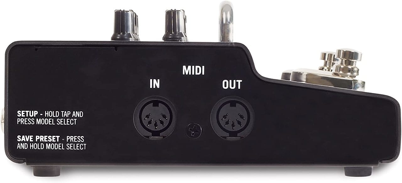
I recently purchased two M5 modelers and an M9 modeler for use on a few pedals boards I am building. These boards are managed by MIDI controllers, so it is important that the M5’s and M9 can pass MIDI information through to the rest of the MIDI chain. Obviously, I was disappointed to find out that the M series of pedals only has hardware for MIDI in and out, but not MIDI thru.
MIDI “thru”, for those of you who aren’t familiar with MIDI gear, is basically just a MIDI jack that sends out an exact copy of the signal it receives on the MIDI “in” jack, except the “thru” signal is buffered to be able to drive long cables and the possible heavy load of whatever the circuit is plugged into. MIDI “out”, on the other hand, is for sending out MIDI signals generated by the M5 or M9 pedal, itself.

On the graphic of the “typical MIDI circuit” above, you’ll notice that the MIDI thru circuit (the circuit inside the dotted line) is basically the same as the MIDI out circuit (at the bottom), the only difference is where the buffered signal is coming from. Some people may wonder why you couldn’t just use a “Y” splitter cable to and plug one split into the MIDI in jack and send the other split to the other pedals. It’s not usually a good idea to use a “Y” cable in this way because you are basically running other MIDI gear in parallel with the driving circuit; if the load gets too heavy, the circuit driving the MIDI signal will not function properly…so that’s why a “thru” jack with it’s own buffer amplifier section is important.
Fortunately, the hardware of the MIDI out circuit is very similar to the hardware needed for a MIDI thru circuit, so it’s relatively easy to turn the “out” into a “thru”. But it would be way more practical if we could have the best of both worlds…to be able to use the MIDI jack as both an “out” and “thru”. All we need for that is a single pole, double throw switch, which can route the MIDI signal from either the pedal microcontroller output (MIDI out) or from the MIDI input jack (MIDI thru). In the graphic of the “modified MIDI circuit” you can see the changes made to the original MIDI schematic…the thru section has been removed, and the SPDT switch is used to handle the signal routing.

Now for the practical application…
Note: Most of the pictures of me modding the circuit will be on the M9 circuit board, but I’ll try to word things in such a way that applies to either model. I have successfully modded both my M5 pedals in this way as well. The same principles could also be applied to the M13 board, which I have not tried to mod yet.
Another note: The wire I’m using in this mod is 32awg solid core “wire wrap” wire.
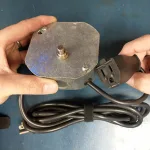
The first step is to disassemble the pedal. I removed all the screws on the bottom to separate the chassis top and bottom. On the M9 I had to remove the 2 screws on the back, and on the M5, I also had to remove the screw in between the MIDI jacks. Then I extracted the main circuit board by removing the screws that are holding it in (on the M9 only) and removed the nuts on the 1/4” jacks. I very gently unplugged the ribbon cable headers. To do this, I had to pick off some hot glue on the ribbon cable with pliers.
Once the circuit board was out of the chassis I examined the circuit board. The MIDI circuit in the M5 and M9 are basically the same. The only difference is the buffer IC. The M5 uses a MM74HCT14M, which is a hex inverting Schmitt trigger, and the M9 uses a MM74HC04 which is a hex inverter (at least on the models that I have). They are functionally identical in this application and the pin-out is also conveniently the same. I imagine Line 6 just used whatever buffer IC they could easily obtain whenever they were on these particular production runs.
I located the hex buffer IC and made a note where pin 1 was. On this pedal, this pin is connected to the trace coming from the pedal’s microcontroller. I followed this trace, using my multimeter’s continuity function and found a via that trace is routed through. In case you don’t know, a “via” is a tiny plated hole on the circuit board that allows the signal to be routed to the other side of the board, it also happens to be a convenient place to solder a tiny wire to. You can see in the picture where the via is that is connected to this trace. On the opposite side of the board, I scraped off the solder mask on this via so that I could solder a wire to it…the other end of this wire will be attached to one of the side pins of the SPST switch. When soldering a wire to a via, it is helpful to enlarge it’s hole by using a dental probe (or something like it) so the wire can slide into the hole before you solder it. I also used a continuity test to double check to make sure I was soldering to the correct via. It’s easy to mess up…I’ve done it before on other boards!


This via on the M5 board is much further away from the buffer IC than on the M9 board. It’s much closer to the microprocessor IC. Here’s a picture of the M5 board:
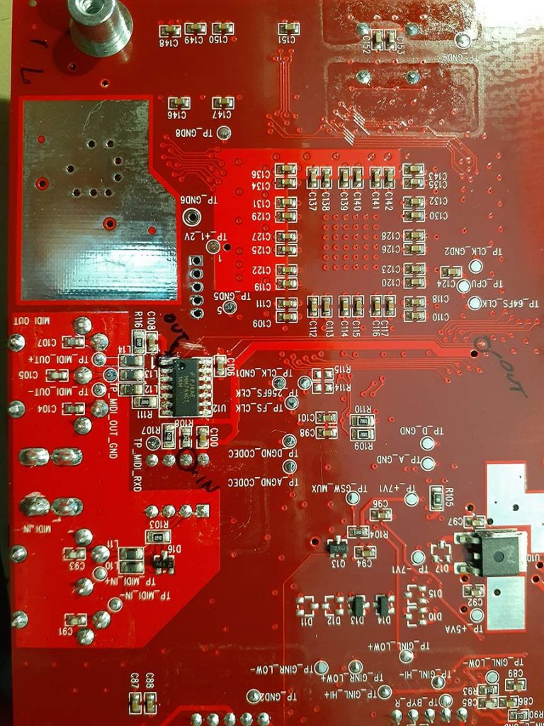
On that same trace that is connected to the buffer IC, somewhere between pin 1 and the via, the trace needs to be cut. I use an Xacto knife for this task. It’s important to cut the trace somewhere there isn’t any other traces around so you don’t accidentally slice any other traces. I usually make 2 cuts on the trace and try to pull up the copper piece between the 2 cuts. That way I definitely know the trace is not connected anymore.
On the same side of the board that the via wire was soldered to, I found pin 6 on the optocoupler IC. This is the pin on which the MIDI signals enter the pedal, through the optocoupler. I soldered a wire to this pin. The other end of this wire will be soldered to the other side lug of the switch.
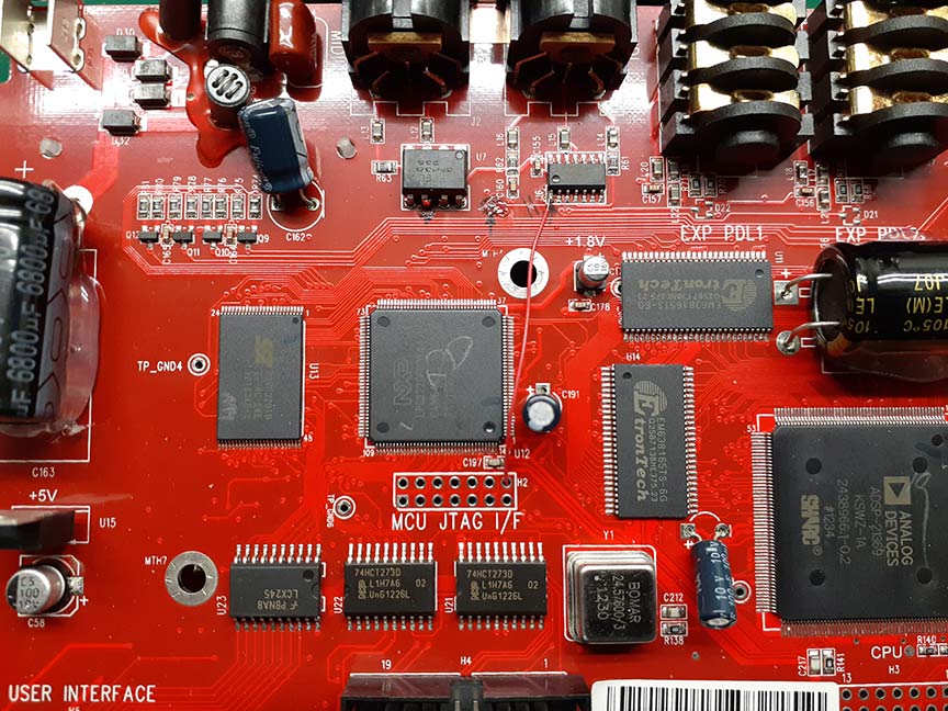
I soldered the last wire to pin 1 of the buffer IC. The other end of this wire will be soldered to the center lug of the switch. I did have to route this wire to the other side of the board, the same side that the other wires were soldered to. I used a hole in the vacant JTAG port to route the wire through.
Here’s the M5 board with wires attached to the solder points:
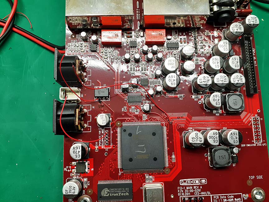
Once all the wires were soldered to the board (and routed to the correct side of the board) I soldered the wires to their respective lugs on the switch. Be sure to keep in mind where the switch will be located on the chassis so give yourself enough wire length.
Then I used hot glue to hold them in place. These wires are very tiny and are easily broken so this step helps keep them from breaking during the rest of assembly, and also electrically isolates the pins from shorting against anything else.

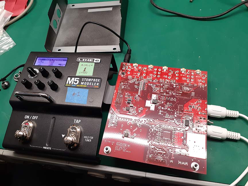
The next step is to test the function of the MIDI thru. My plan to do this was to hook up some MIDI pedals to see if I could control them through the Line 6 pedal. I reattached the ribbon cable and laid out the open chassis on my bench. I hooked up the MIDI cables to all the involved pedals. I made sure no part of the chassis (or anything else) was shorting the circuit board and then I applied power. Everything ended up working correctly!
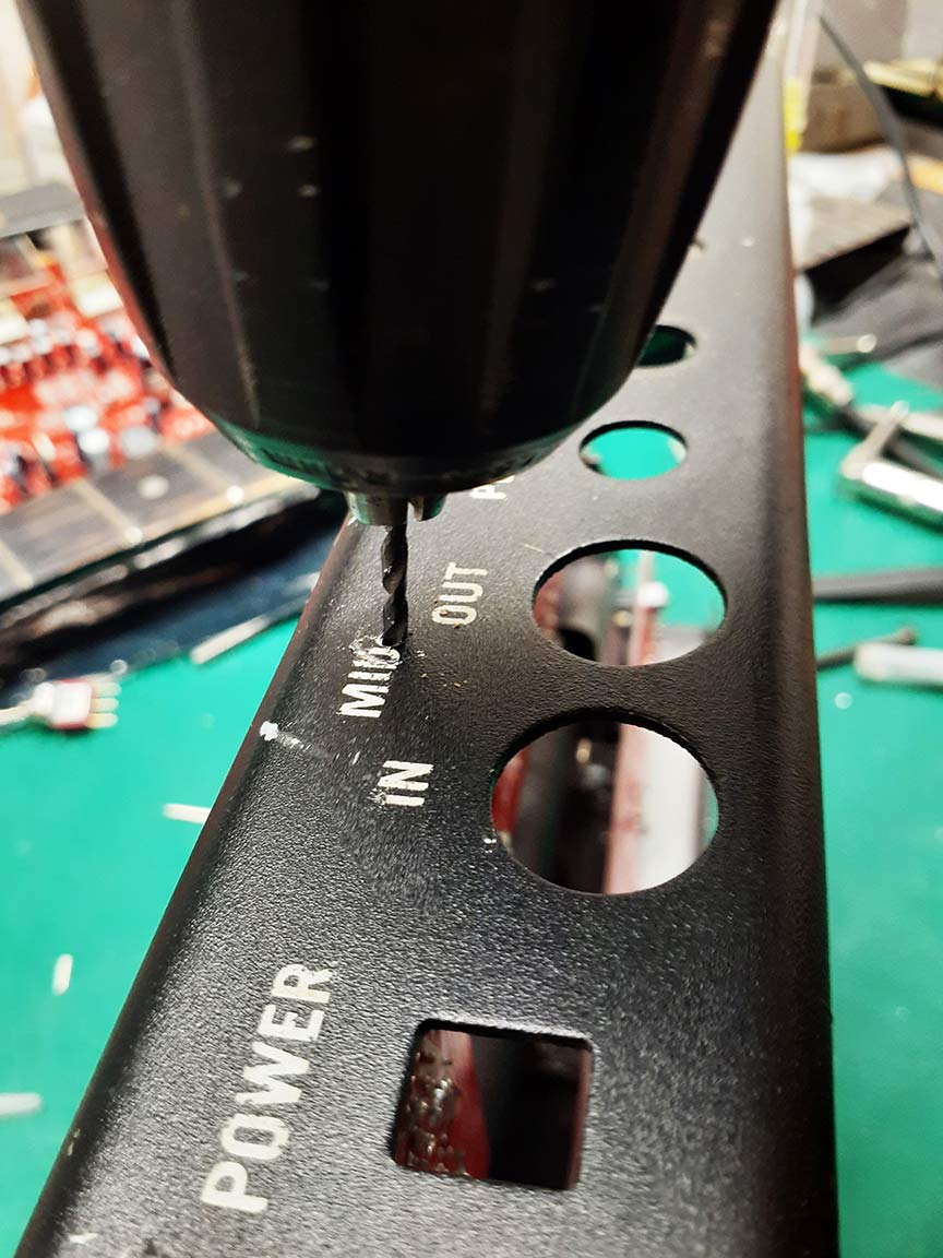
Next, I drilled a hole in the chassis for the toggle switch to fit in. This step seems simple, but a lot of thought has to go into where the switch will physically fit, and how possible or easy it is to reassemble the pedal with the switch in place. This is another reason to give yourself enough switch wire length.

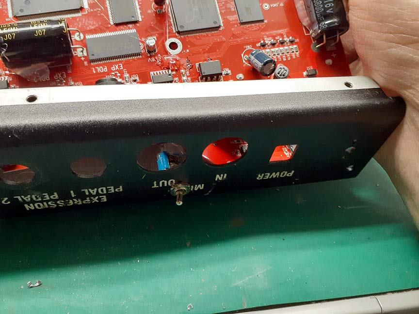

Here’s the M5 after the mod:

Once the pedal was back together, I tightened up all the screws and nuts and placed it on my pedal board. Now I can route MIDI signals through this Line 6 pedal to all the other pedals on my board!