- Your cart is empty
- Continue Shopping
Bluetooth Camera Shutter Footswitch
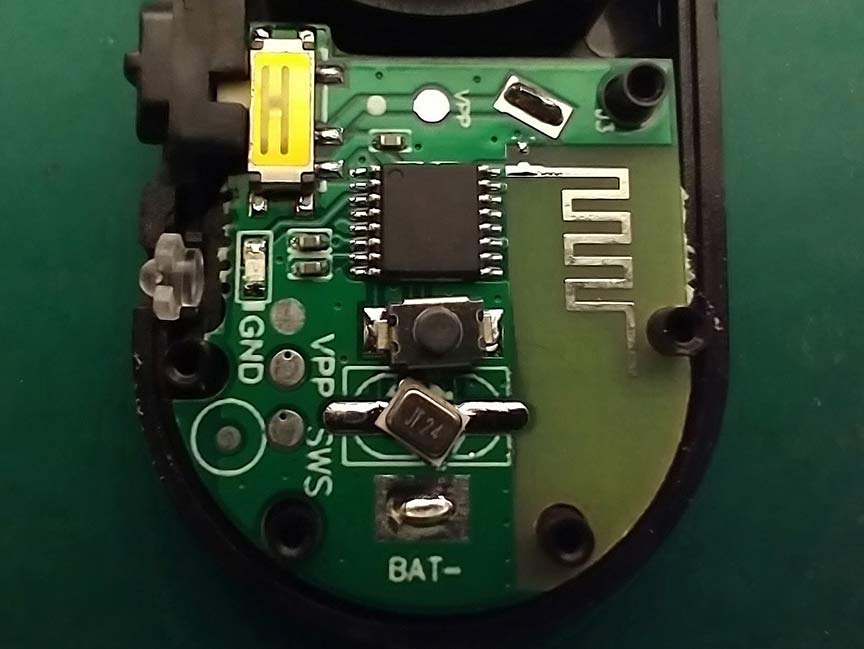
A way to take blog photos while my hands are busy.

In the process of writing these blogs I’ve realized that it is very difficult to take photos of a circuit board that I am working on while my hands are holding tools. Even if the camera is on a mount, It’s still nearly impossible to take photos while I am working. Since I use my phone to take most of the photos, it occurred to me that I could try to find a Bluetooth footswitch that could trigger my camera app’s shutter button. Unfortunately, it wasn’t as easy as I thought it was going to be to find such a device. I found a lot of readily available hand-held button devices that work well for this application, but I wasn’t able to find any that were built into a footswitch. Fortunately, I’ve never been one to let limited market availability deter me from getting something that I needed…Let’s DIY this thing!
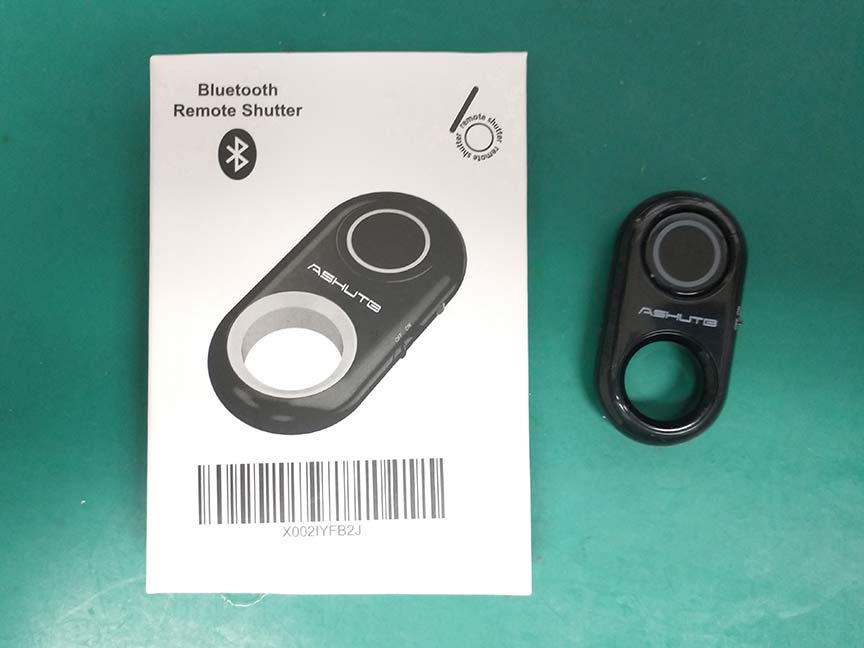
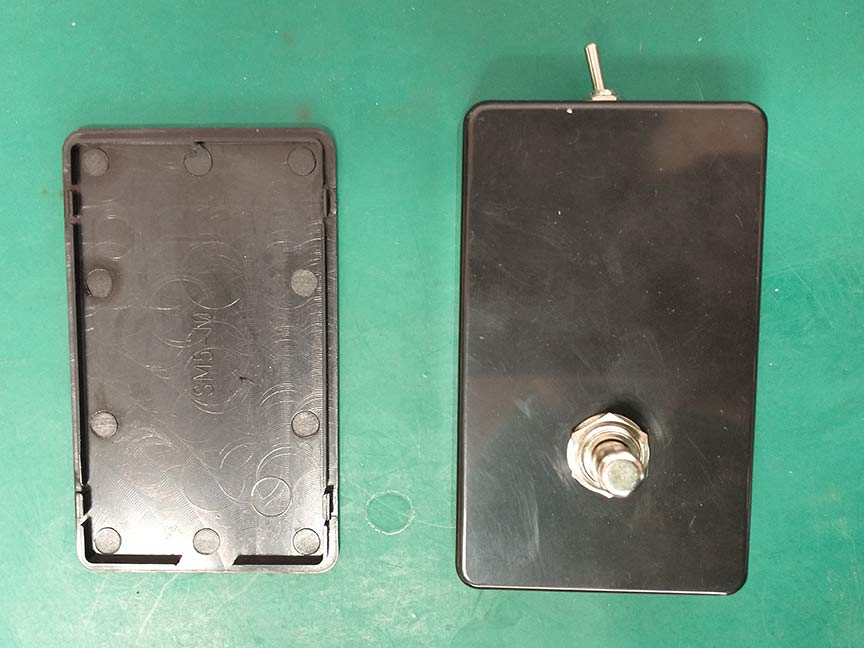
I got one of the hand-held Bluetooth devices with the intention to build it into a footswitch enclosure. There’s not much design involved with something like this, it’s mostly just re-wiring switches that already exist on the dongle. One design decision I made is that I am intentionally using a plastic enclosure for the dongle because I don’t want it to be shielded. If I used a metal enclosure there is a possibility that the box could touch something conductive, increasing the likelihood of the enclosure acting as a shield to the Bluetooth signal. I’ll sacrifice the “toughness” of a metal enclosure for the likelihood of the signal transmitting better in a plastic enclosure.
Basically, I just have to replace the tiny tact switch (for camera shutter control) and slide switch (for power on/off) with more robust switches that can be accessible on the outside of the enclosure….easily done.
The parts I need are: A plastic enclosure, one SPDT toggle switch, one momentary footswitch, some wire, and of course, the Bluetooth device.

- The first thing I did was drill holes in the enclosure. I wanted to put the toggle switch out of the way of the footswitch because I didn’t want it accidentally getting kicked when the footswitch was being pressed. I ended up putting it on the top side of the box.
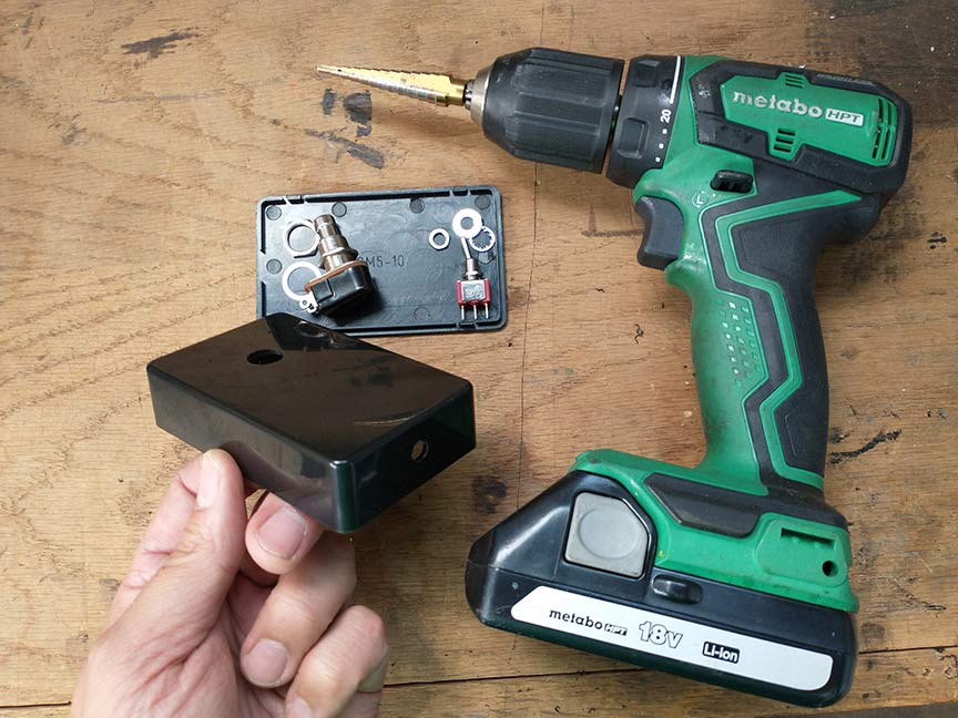
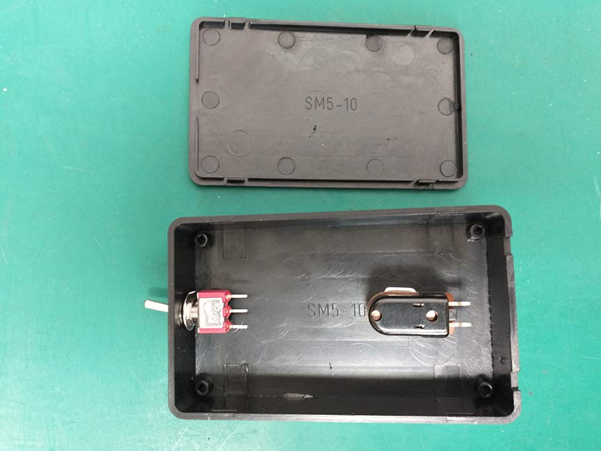
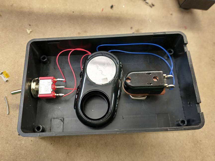
2. I installed the switches in the box.
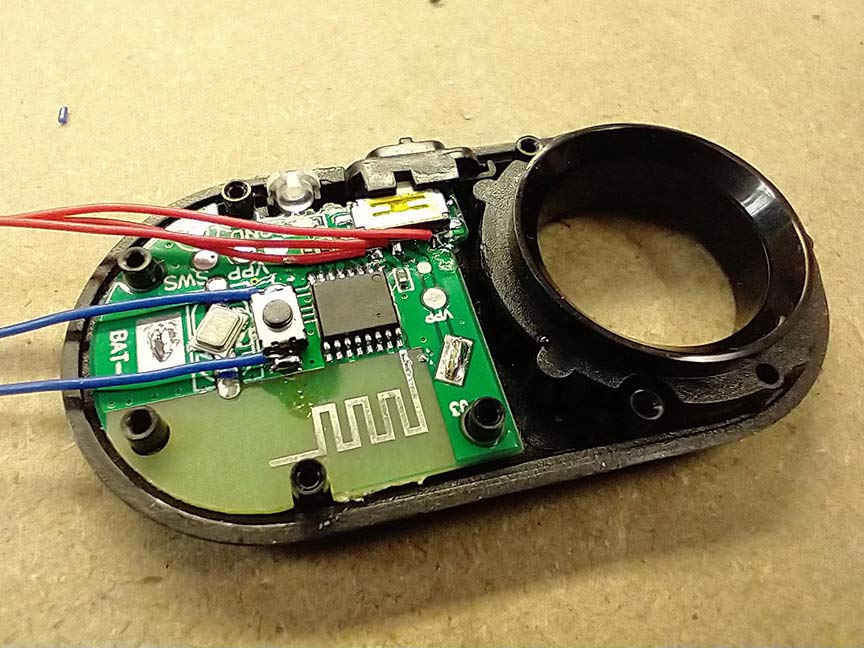
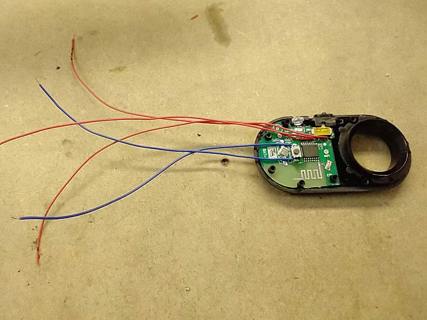
3. Next, I disassembled the Bluetooth device and decided where the wires should be hooked up. There is no need to remove either of the existing switches on the circuit board, we can just run our switches in parallel with the original ones. I am using 30awg “wire wrap” wire for this project because I need the wire to be very small in order to solder to the pads on this circuit board. “Wire wrap” wire is very thin, solid-core wire used in a prototyping technique in which connections are made when the wire is wrapped around component leads. This technique is not used much anymore but the wire is still very practical for running jumpers in projects like this.


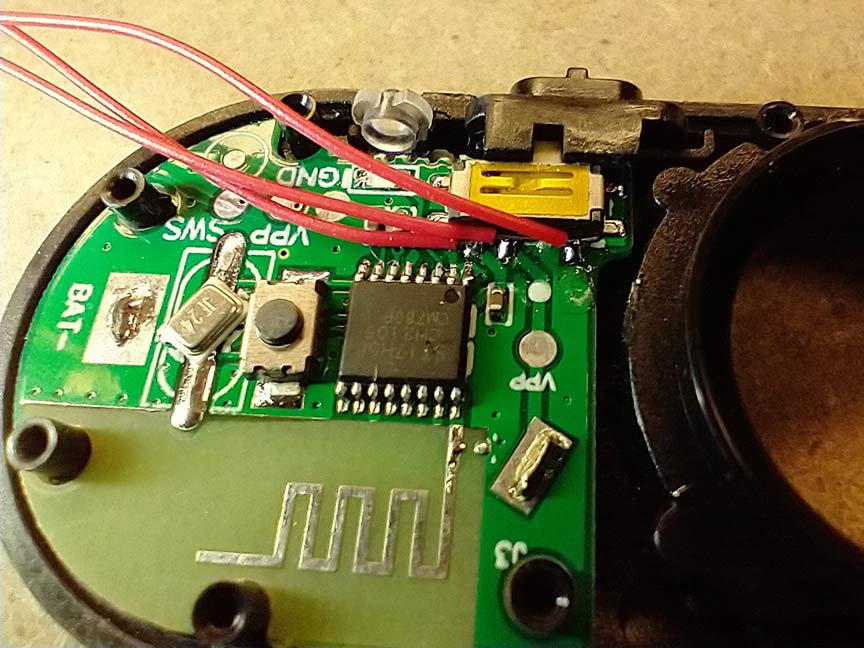
4. I soldered the wire to the leads of both switches. In working with components this small it is sometimes necessary to use a magnifying glass or observation microscope to check the solder joints for shorts.
I used a marker to make lines on the 2 outside wires of the slide switch so I could know which wires to attach the to 2 outside wires of the new toggle switch (the unmarked wire goes to the center pin). The tact switch pins are interchangeable so they don’t need to be marked. Then I covered the solder joints with hot glue to keep them from moving around and breaking during the rest of the build process.


5. Finally, I re-assembled the cover on the Bluetooth device. I just had to make sure the wires weren’t pinched between the plastic cover pieces so I didn’t press them together too much. This step is probably not too necessary, but I wanted to protect the circuit board as much as possible.


6. Now it’s a simple matter of wiring up the switches in the box. Once the wires were soldered, I used hot glue to attach the Bluetooth device inside the box. I made sure the device’s battery was accessible.

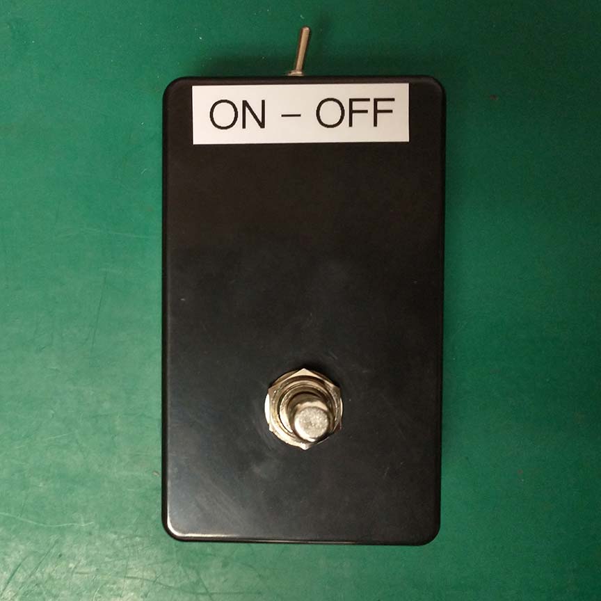
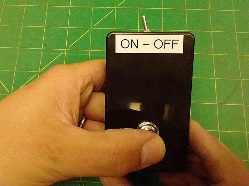
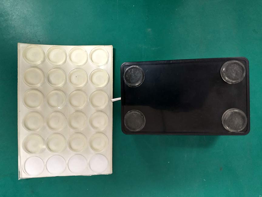
7. I added the battery and tested it (the first 2 pictures below were taken as I pressed the button). I had to figure out which position of the toggle switch was on and off (by deduction). Once I figured it out, I added a label to the top. The I attached some rubber feet to the bottom so it wouldn’t slide on the floor when I pressed the switch with my foot.

That’s how I build my Bluetooth footswitch. Here’s my new setup for taking blog pictures: