- Your cart is empty
- Continue Shopping
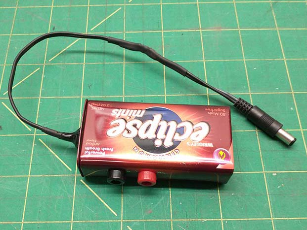
DIY Pedal-Current-Tester-Thingamabob
Making a tool to measure the current draw of a pedal.
As an electric guitar player, who regularly wires up pedal boards, I often need to know how much current a particular pedal is drawing. This is important information when deciding how to power certain pedals on a pedal board. If the pedal has a low enough current consumption it can be powered via a daisy chain with several other low current consumption pedals (in a parallel powering configuration). But if the pedal has a relatively high current draw then it needs to be powered with it’s own isolated supply. This all has to do with reducing the possibility of ground loops, in which current flows through the ground path within a series of pedals. If the current draw is low enough through a series of pedals, the current flowing in the ground loop won’t be audible through an amplifier. But on the other hand, if the current draw of the series of pedals is high then the ground loop will be audible, usually creating hum in the amplifier.
…All that to say it’s necessary to know which pedals will work well powered together and which ones won’t. Enter the “DIY Pedal-current-tester-thingamabob ” (if you can come up with a better name for it, good for you, use that instead!).
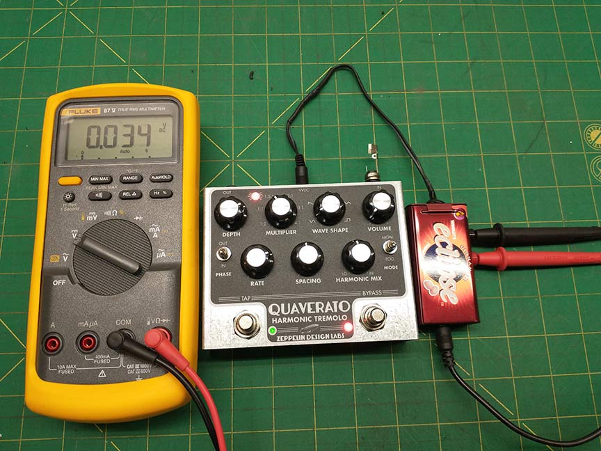
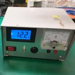
The concept is very simple, and has been a tried and true method for measuring current for decades…we’ll use a 1 ohm resistor in series with the pedal’s power supply and measure the voltage drop across it with a voltmeter.
According to ohms law, the voltage drop across a device is directly proportional to the current flowing through the device.
V=I*R, in words: (Voltage drop across a device, in volts) = (current through the device, in amps) multiplied by (the resistance of the device, in ohms).
As you can see, if the resistance of the resistor is 1 ohm the current through the device is equal to the voltage across the device. In our application, all the current the pedal uses will go through the resistor, so the voltage we measure across the resistor (in volts) is the same as the current draw of the pedal (in amps).
Seeing that all the power to the pedal is going through this resistor, we need to decide its power requirements. Resistors are designated mainly by their resistance and their power dissipation. We know its resistance is going to be 1 ohm, so now we need to know how much power it needs to dissipate. I figure at the worst case scenario a pedal that we’ll want to test will draw 500mA of current. That means that there will be a 500mV drop across the resistor, and the pedal will receive 8.5V out of the 9V from the power supply…and most pedals can operate fine with 8.5V. But the power the resistor will have to dissipate (in watts) is defined by the product of the voltage drop across it and the current flowing through it…in other words, Power = Voltage * Current. So in this case (.5V) * (.5A) is .25 watts. As a general rule in cases like this, I like the resistor power dissipation capability to be double the expected power dissipation….so a ½ watt resistor should work in this application.
**Side note: If you are at all interested in working with electronics, in a design or even repair capacity, a basic requirement is having an intuitive understanding of Ohm’s Law. Think about it, visualize it, and digest it until you are fully confident of how electrons are flowing through resistors and how any parameter change alters that flow.**
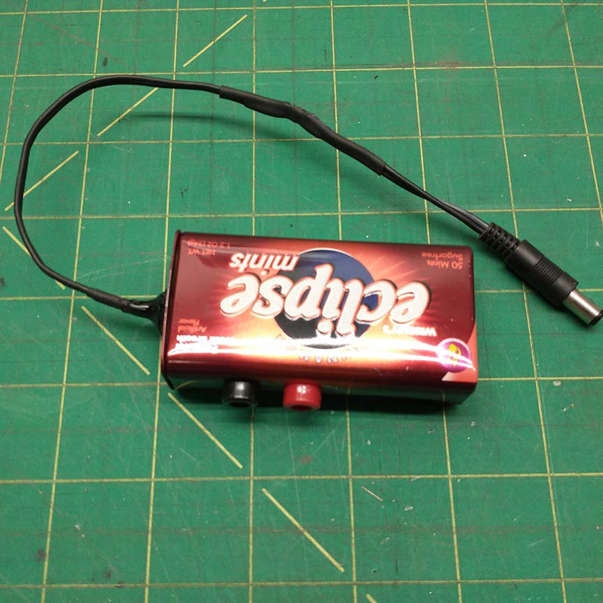
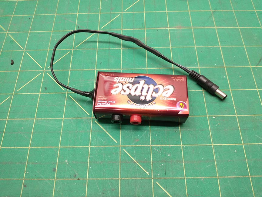
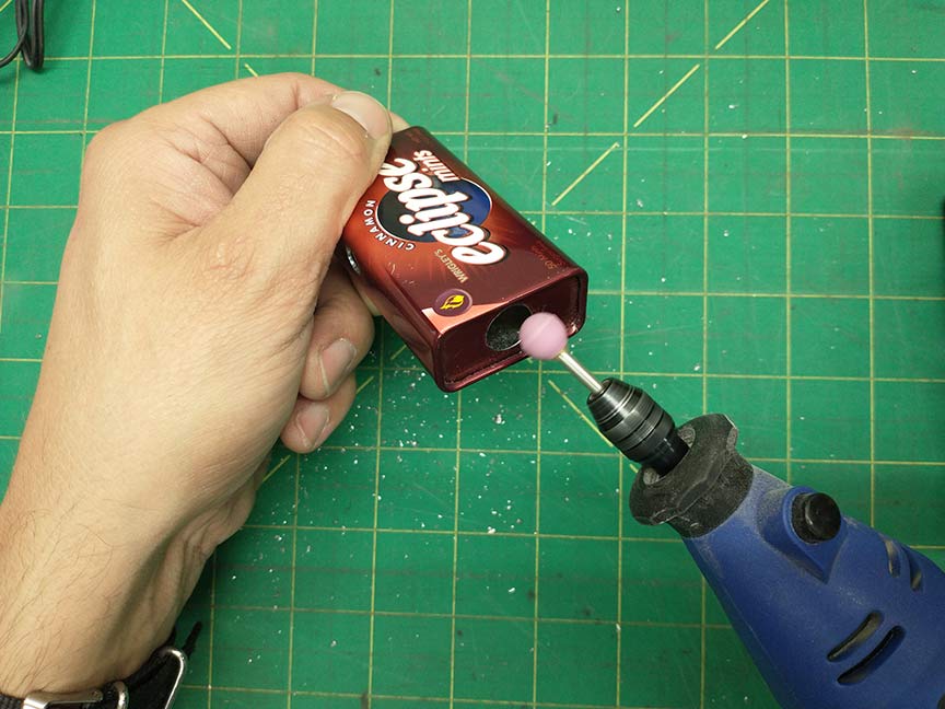
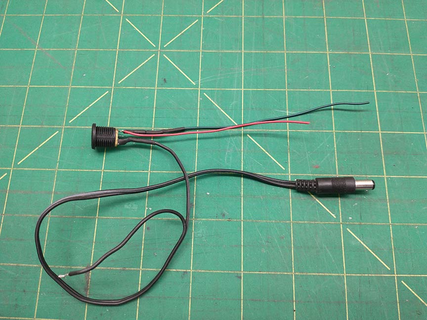
For this project I will use the male barrel jack from an old wall wart that I found. I also found an old breath mint container that we can use for the chassis. We’ll also need 2 multimeter probe tip jacks and a panel mount female barrel jack, some hook-up wire, as well as a 1 ohm resistor rated for at least ½ watt.
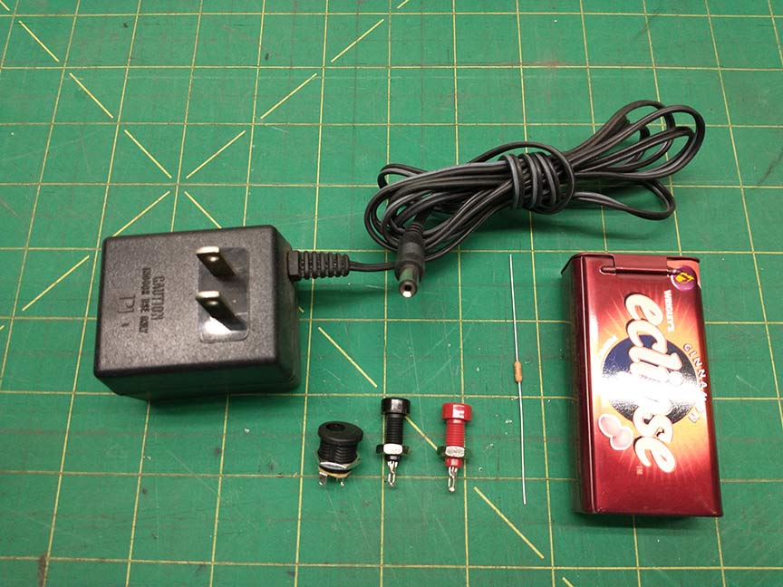
I opted to use a .5% tolerance resistor…which means that the actual value of the resistor will be between .995 ohms and 1.005 ohms. That’s overly accurate for this application, but it’s comforting to know the resistor won’t be the weak link in the accuracy of this system (which will probably be the contact resistance between the multimeter probes and the probe tip jacks).
The wiring for this device is pretty simple. Here’s a diagram of how everything should be wired up:

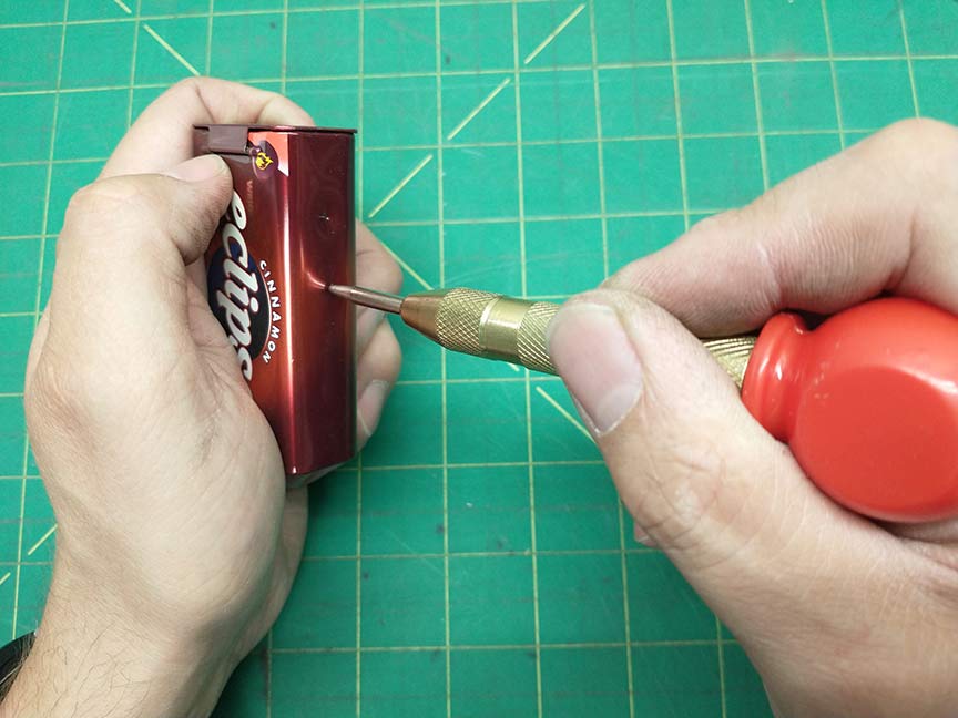
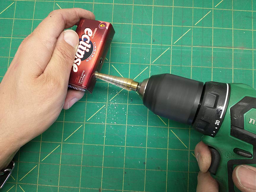
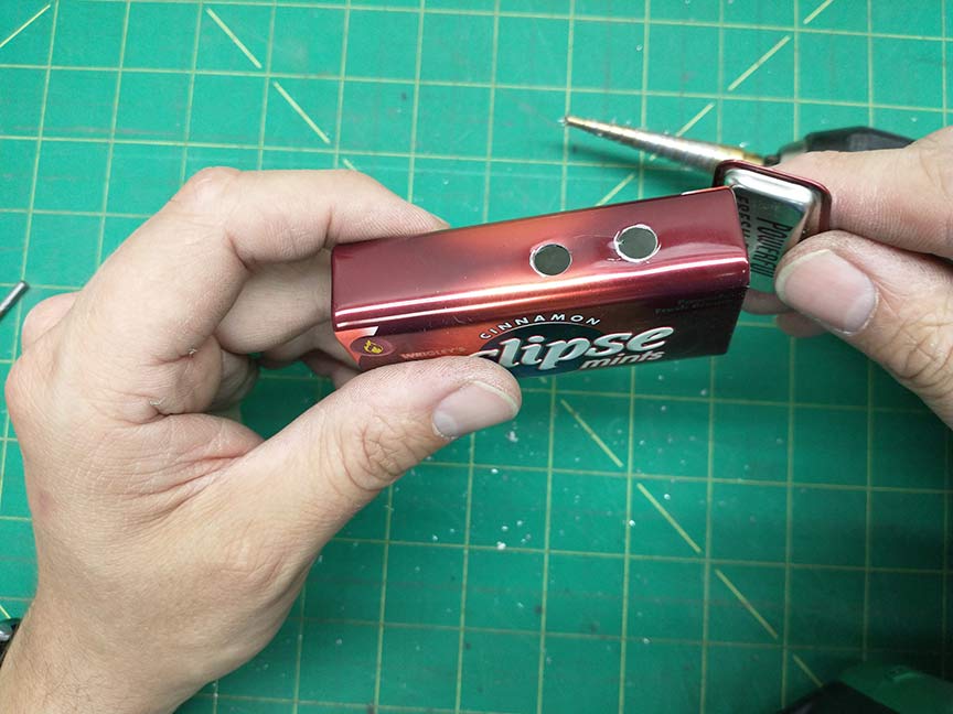
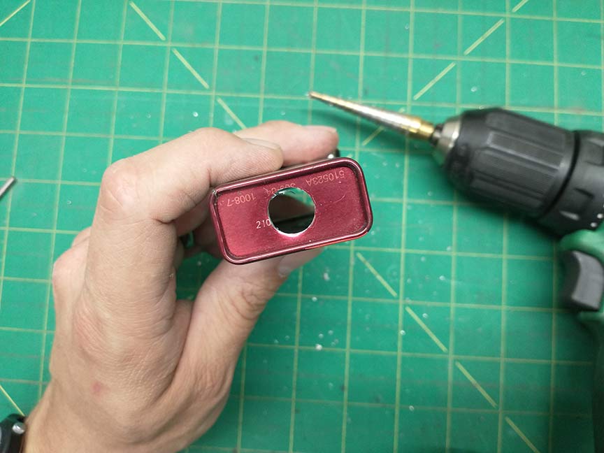
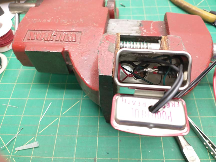
- The first thing you’ll need to do is drill some holes in the breath mint container for tip jacks, female barrel jack and male barrel jack output wire. The tip jacks go on the side and the female barrel jack goes on the bottom of the container and the output wire goes on the top. I used a center punch to mark the holes before I drilled. You may want to de-burr the holes somehow (I used a Dremel and a spherical grinding bit).
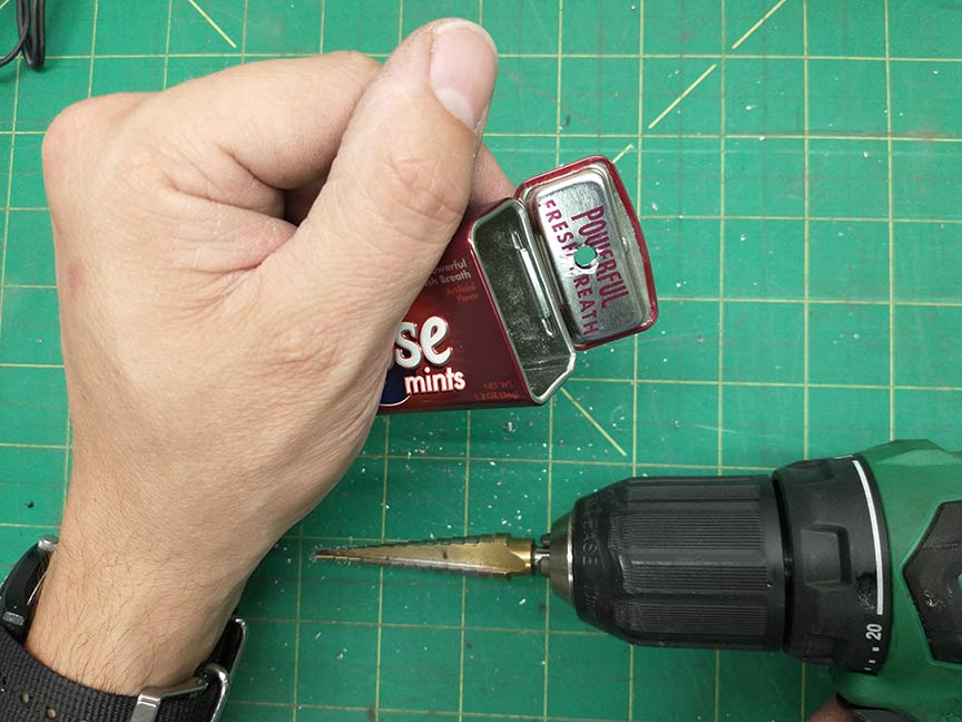
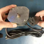
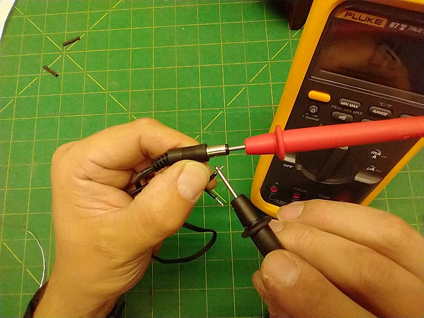
2. Next, you need to clip the male barrel jack from the wall wart and find which wires are connected to the positive and negative sides of the barrel jack. Strip and tin the wires and use your continuity tester to find out their polarity. Remember the positive should be connected to the outside sleeve of the jack and the negative wire should be connected to the center pin of the jack.
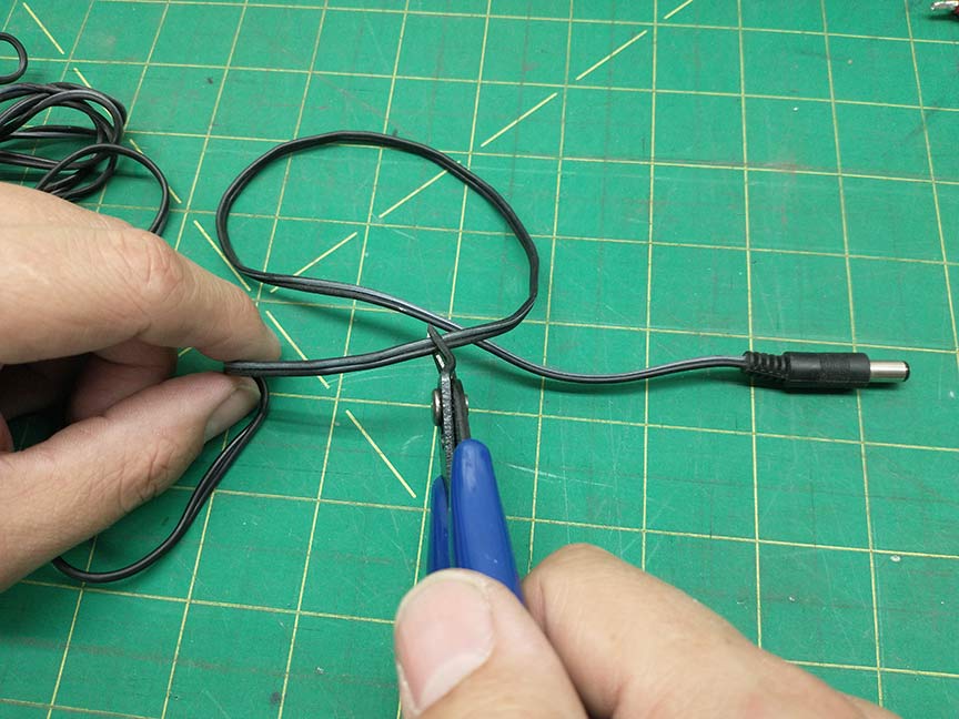
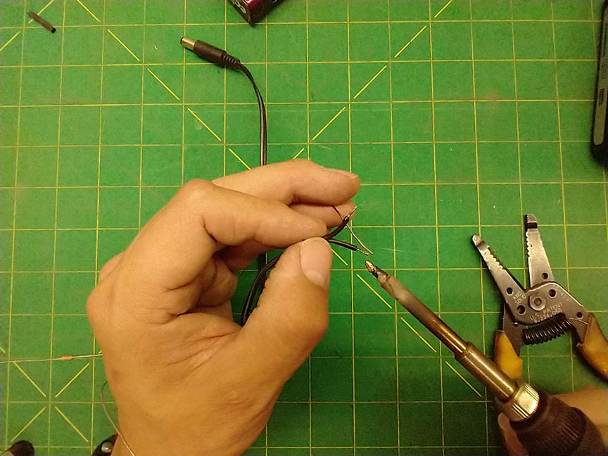
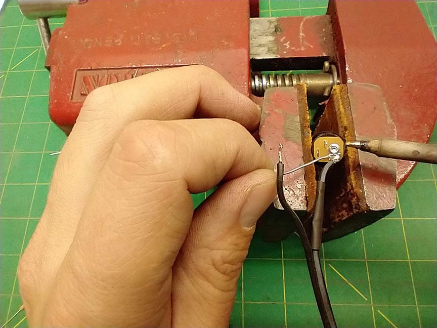
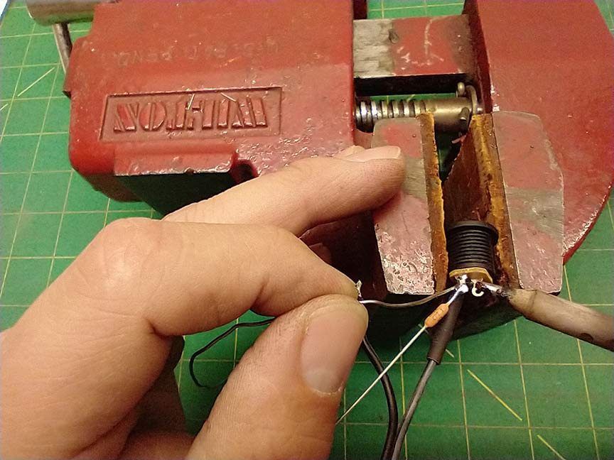
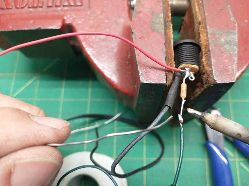
3. The next step is wiring everything up. Depending on the size of the container you use, you may, like me need to make a wiring harness outside of the container. The negative solder lug of the female barrel jack gets attached to the negative wire of the male barrel jack. I ended up wiring the 1 ohm resistor directly to the positive solder lug of the female jack and running wires to the tip jacks from either end of the resistor. Once all the solder joints were done I covered them with heat shrink.
4. The tricky part is installing it into the container. You’ll probably have to use needle nose pliers to screw the nut on the panel mount female barrel jack. It’s kind of a stretch.
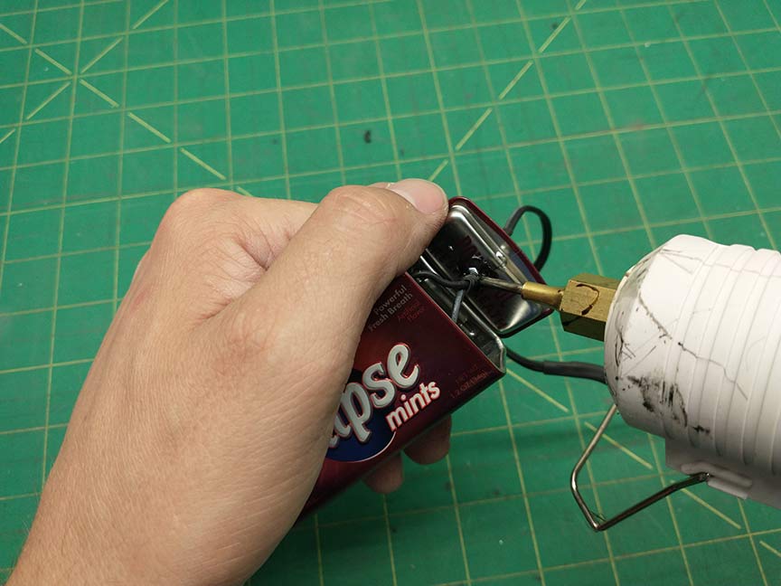
Hopefully you’re not like me because at this point in the process I realized the hole I drilled in the top of the container for the male jack output wire was too small for the jack to pass through. I had to cut off the jack and ran the wire through the hole in the lid and then re-soldered it.
You may also find it kind of tricky to solder the wires to the tip jacks inside the small container.
5. At this point you should use your multimeter to test the connections. Make sure you have around 1 ohm resistance between the sleeve of the female jack and the sleeve of the male jack. Also make sure you have 1 ohm resistance between the tip jacks. Finally make sure the center pin of the female jack is connected to the center pin of the male jack.
6. If everything is hooked up properly, seal hole in the top of the container (where the male barrel jack wires pass through) with hot glue. You don’t want the sharp metal edge of the container to cut through the jack wires.
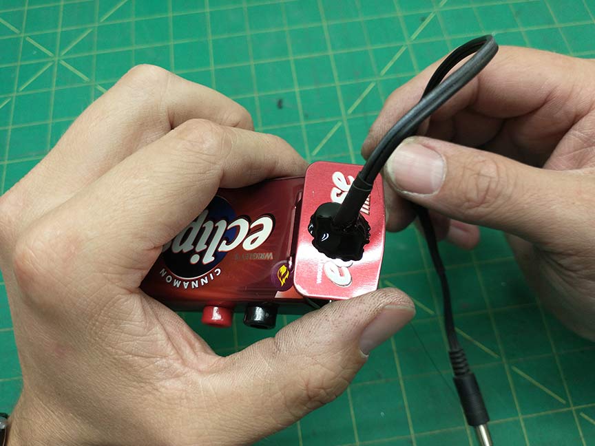
Now start testing your pedal’s current draw!