- Your cart is empty
- Continue Shopping
A DIY Variable AC Power Supply
Using a Variac to create a practical lab test tool
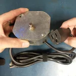
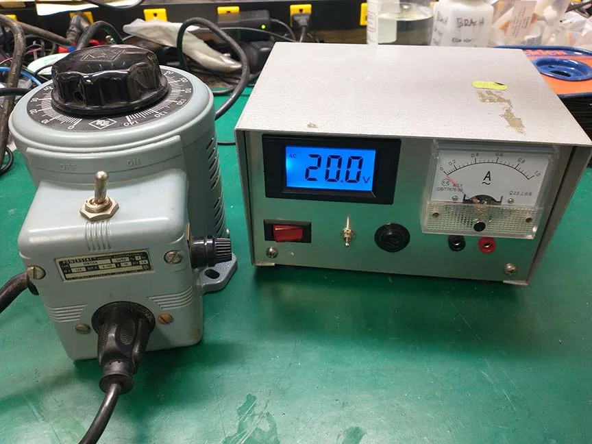
I was recently given a Variac. A Variac is a variable autotransformer that can output voltage from 0VAC to around 140VAC. The term “Variac” is actually a U.S. trademark of the General Radio Corporation, but the term has become ubiquitous for any variable autotransformer.
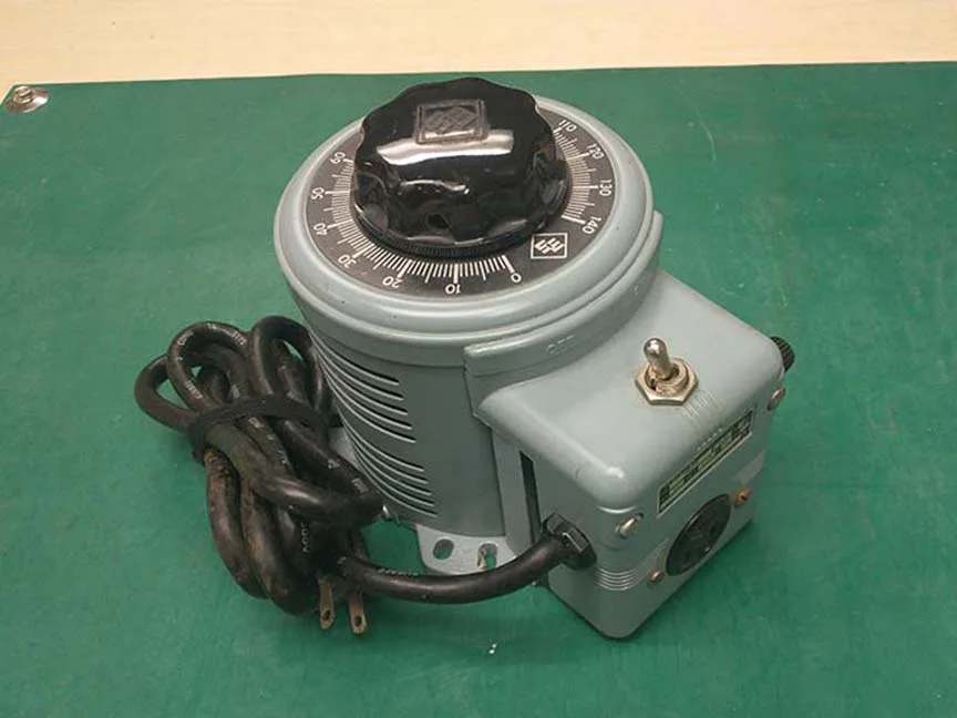
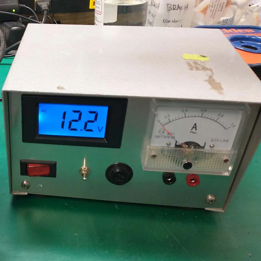
Although I have a few variacs already, this was the first one I owned that didn’t have a built-in voltage and current meters. The voltage meter is useful to know the variac’s output voltage. The current meter is very helpful to know how much current is being drawn by the device the variac is powering, which is very helpful in dealing with broken equipment that keeps blowing fuses.
Since this variac wasn’t as useful to me because it didn’t have either of these meters, I decided to use this variac in conjunction with a 115 to 36V step down transformer to make a low voltage variable ac power supply.
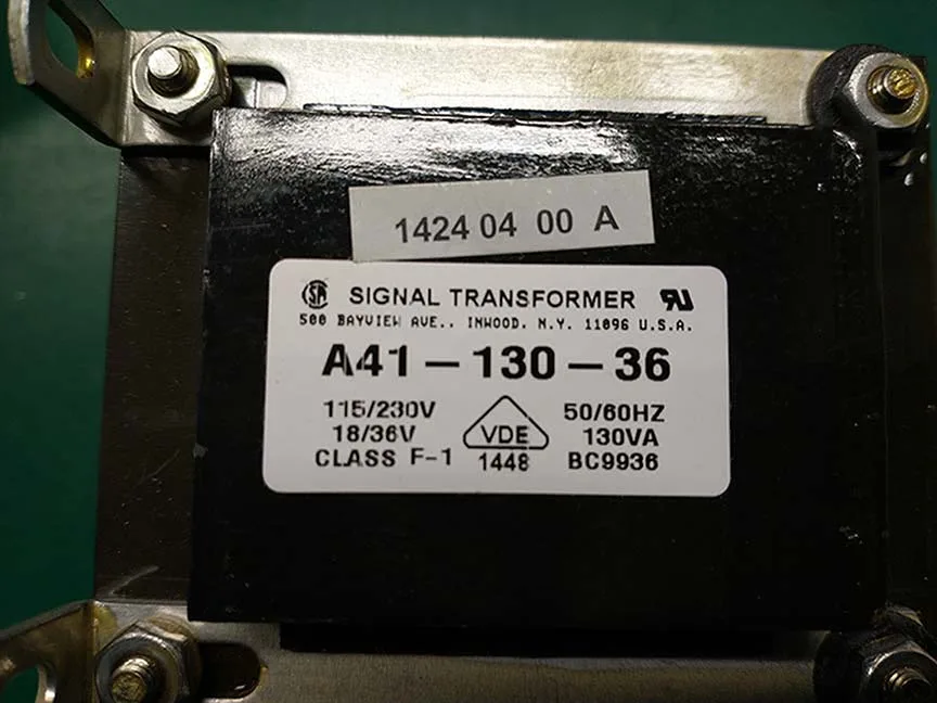
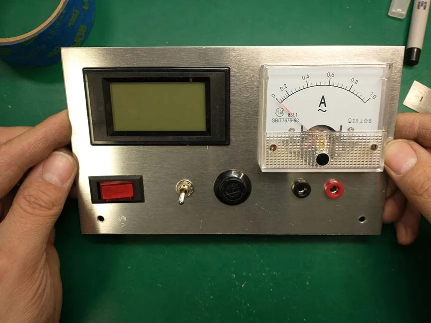
Low voltage AC power supplies are an important tool for any electronics lab. They are useful in several tasks that I do on a regular basis, such as designing linear power supplies, testing the current draw of broken equipment, as well as testing the winding ratio and other parameters of transformers I either wind or rescue from discarded equipment. Although it is technically possible to just use a vairac for these tasks, the low voltage variable AC power supply has some features that make it a much better tool for these jobs. First of all, the autotransformer in the variac isn’t fully isolated from the electrical mains. Only one leg of the autotransformer is being transformed, leaving the other leg tied directly to the electrical mains. When dealing with any type of electronics, it is always best to fully isolate the power legs from the mains through a transformer (or some other isolation device). That way, there is at least one inductively coupled coil between you and a near infinite supply of current (or whatever the outlet’s power breaker is rated for). Another reason a low voltage power supply like this is better than a variac has to do with voltage accuracy. This power supply transforms the voltage coming from the variac and steps it down by a ratio of about 120:40 (or 3 to 1). So theoretically, it is 3 times easier to dial in a specific voltage (i.e. more accurate) than just using the un-transformed variac voltage. Some other features of this variable AC power supply are that it has fuses for both sides of the transformer, as well as meters for both current and voltage. In applications like this I like to use analog current meters (instead of digital current meters) because you can easily see the needle rapidly moving up as you turn the variac’s dial if there is a short or something in the equipment that is being powered. On the other hand, I like to use digital voltmeter because they are easier to read. The only annoying thing about using a digital voltmeter is that they need their own DC power source for them to work. So for this project I used a 9V DC wall wart to supply its power.
I got all the parts (that I didn’t already have) from Aliexpress. It cost about $15 to get what I needed, so it was a pretty inexpensive project considering the useful tool that came out of it.
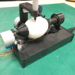
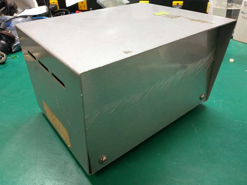
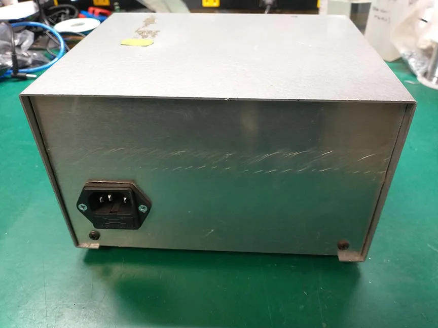
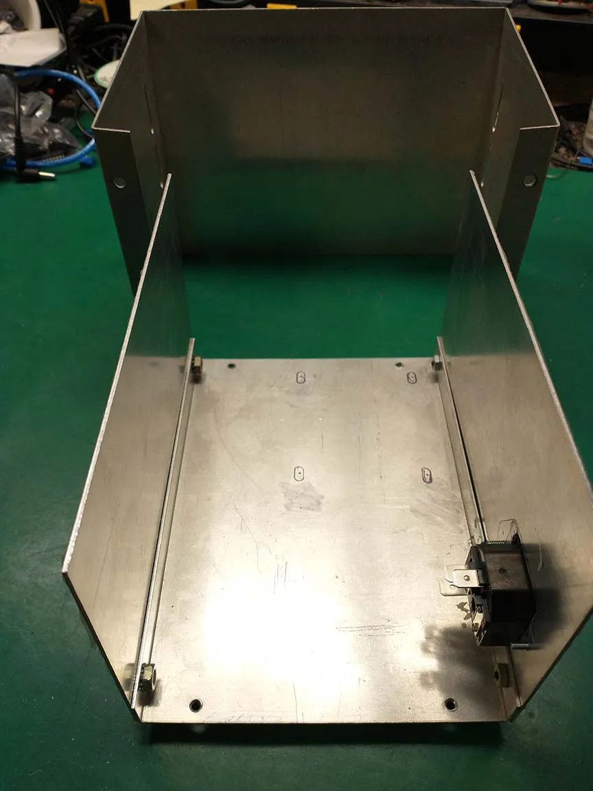
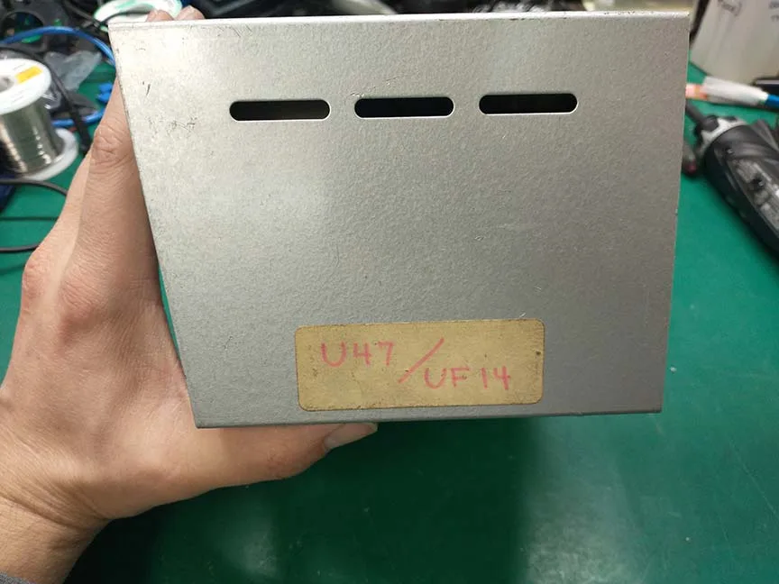
I was given a project box from my friend who owns a recording studio. The box used to house a power supply for an old (U47) tube microphone, but I cleaned it up and replaced the front and back panels. It was the perfect size for this project’s application.
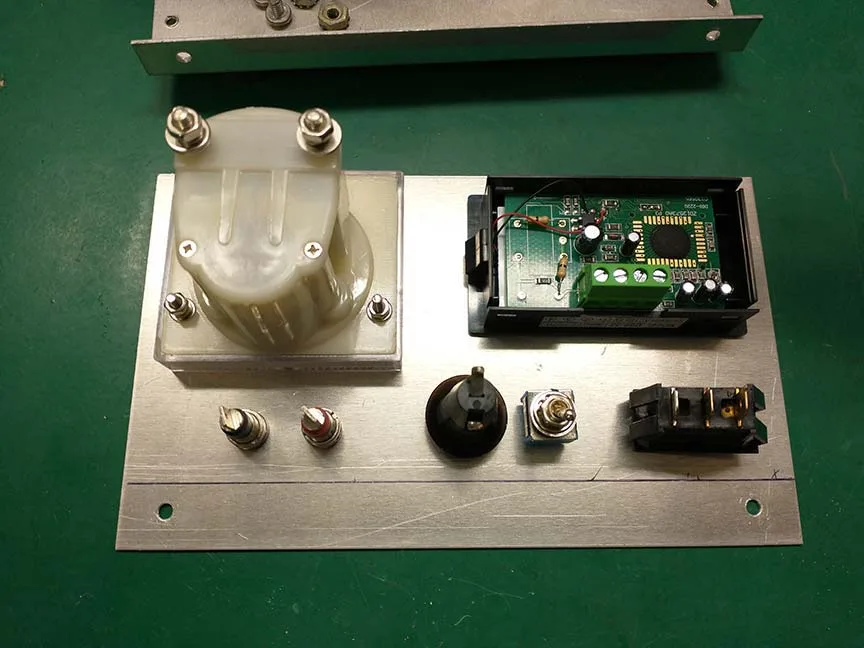
I removed the front panel and I carefully laid out all the components on the front panel to see how it would all fit together.
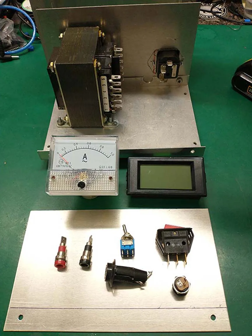
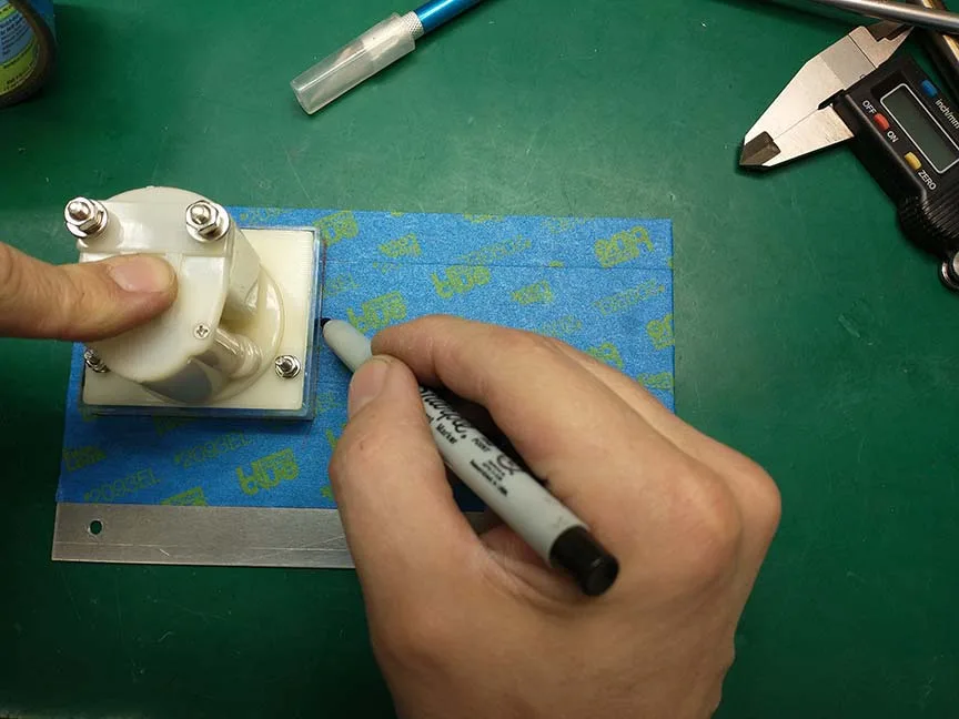
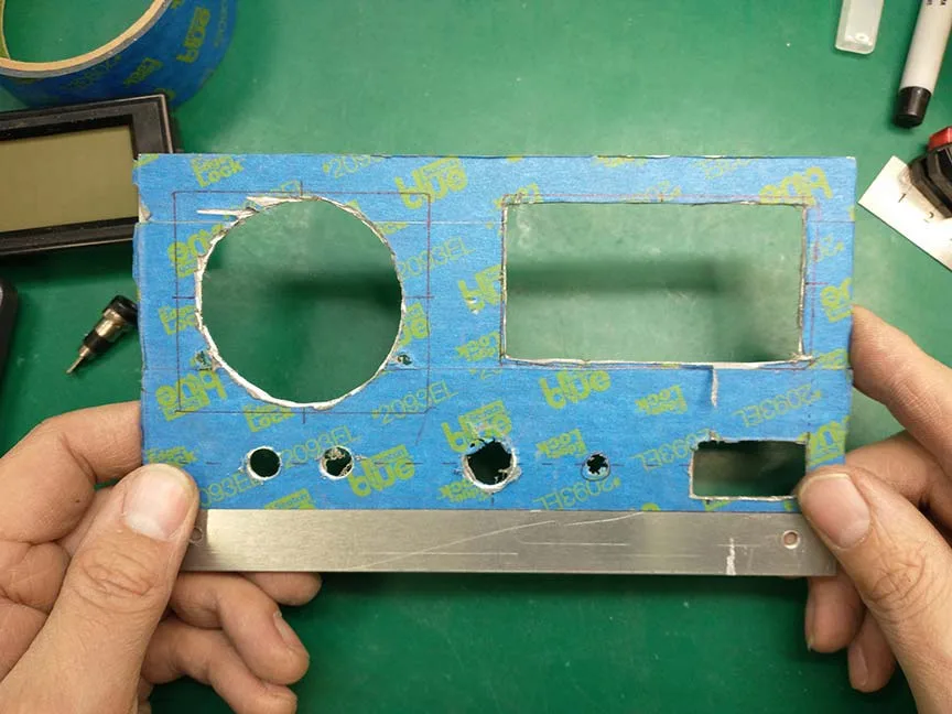
I added masking tape on the front side of it so it wouldn’t get scratched up when I was drilling and cutting the holes. It also gave me a good surface to draw my cut and drill marks on when I outlined where all the holes needed to be.
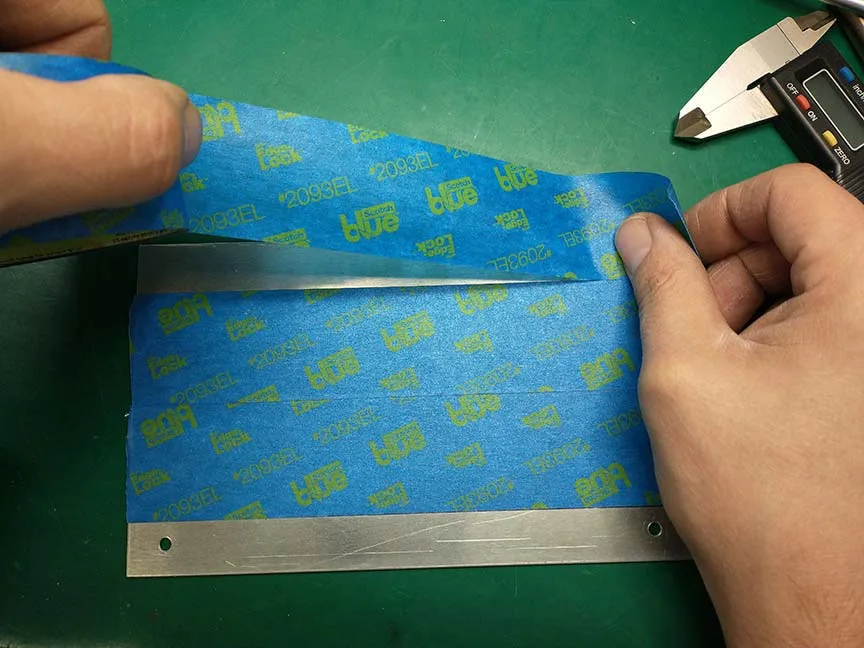
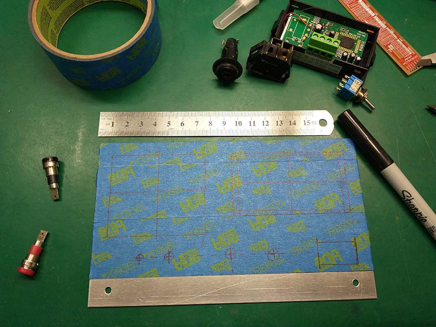
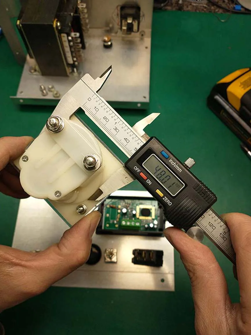
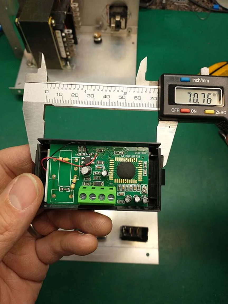
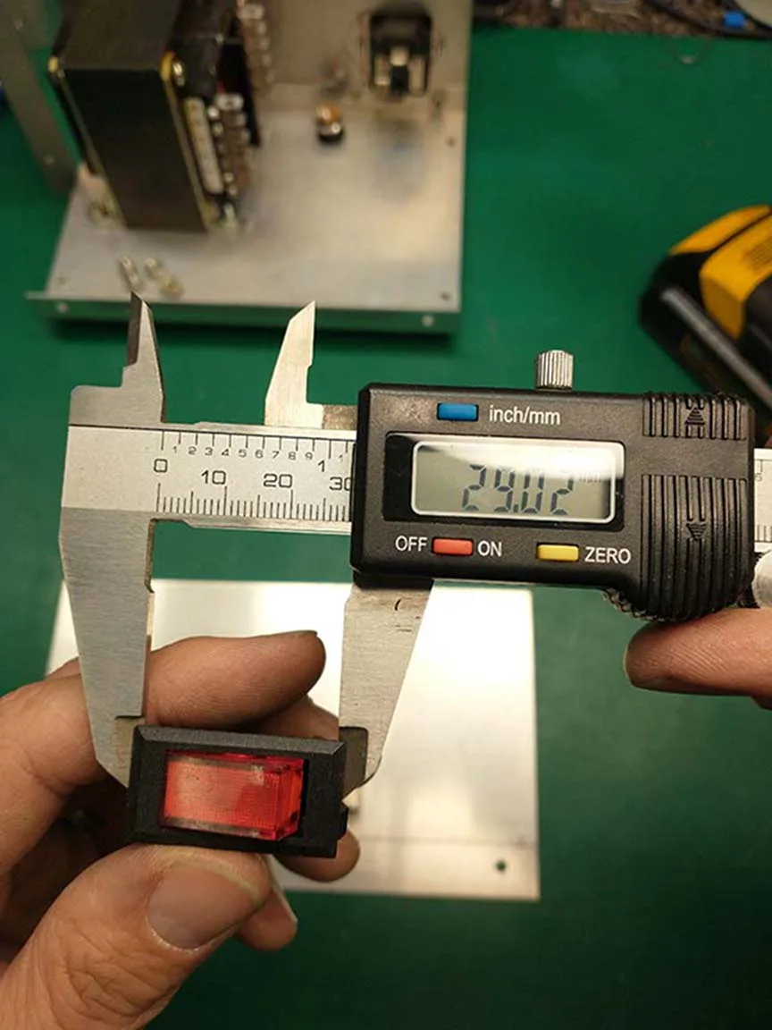
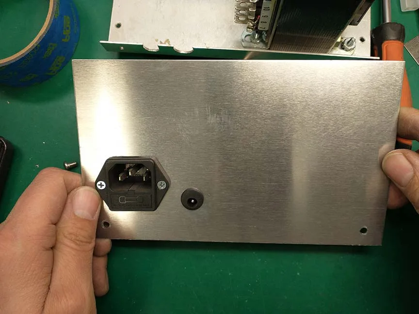
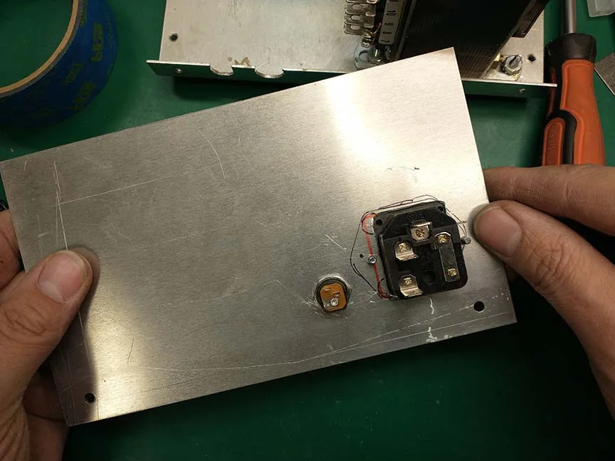
I measured all the parts with my calipers so I knew how large to make the holes. I also marked and drilled the base of the chassis for the transformer mounting holes, and I drilled a hole in the back panel for the voltmeter’s DC power jack.
Conveniently, the IEC (power) jack was already installed, which saved me some effort. This step was the longest and most tedious step of the whole process. Chassis work is always time consuming.
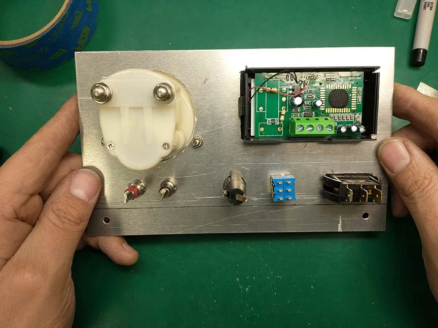
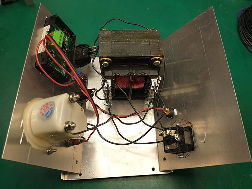
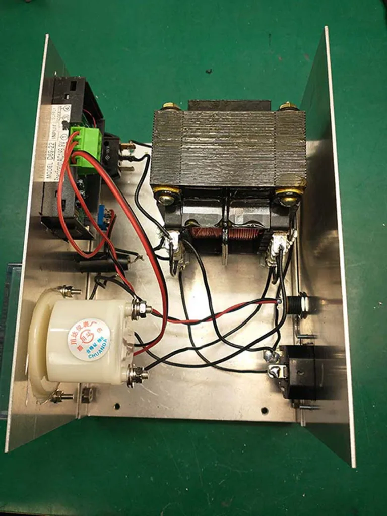
After the holes were drilled and cut, I was able to install all the panel components, including the transformer. I used a Dremel cut-off wheel to cut most of the larger holes. I used a drill press for the smaller holes.
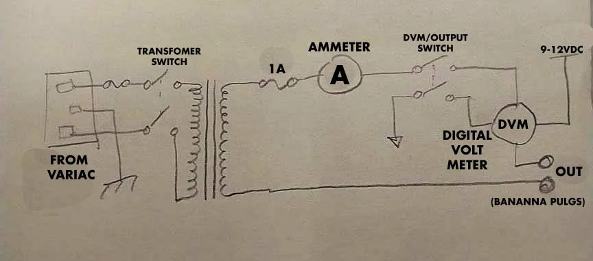
Once all the components were installed, the next step was just wiring everything together according to the schematic. I just drew this schematic out on a post-it note. I added some text labels on the computer to make it a bit more descriptive for this blog.
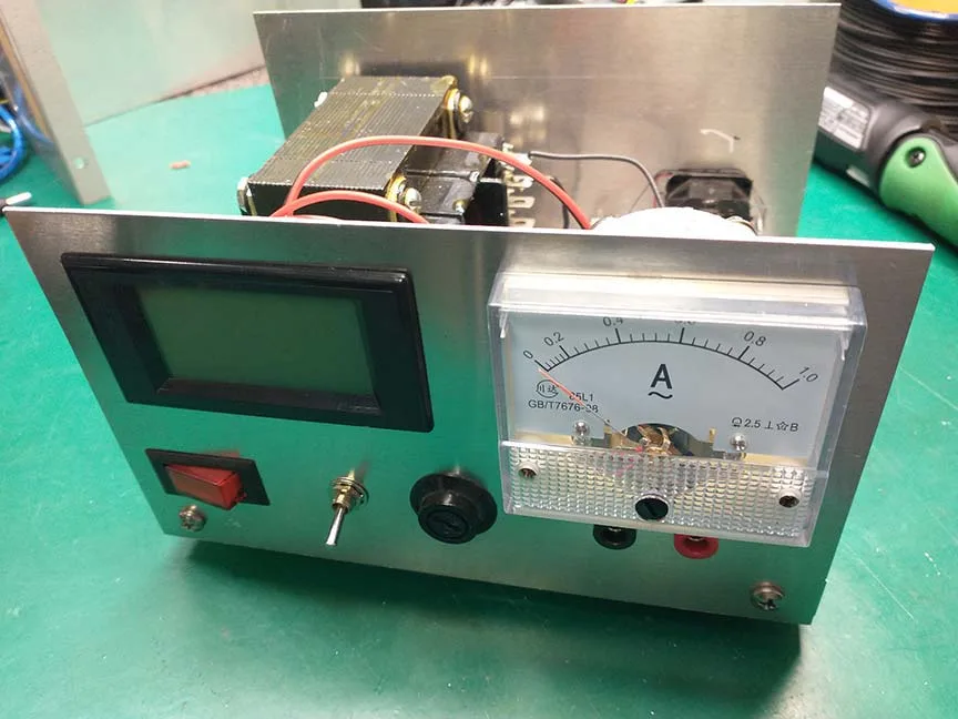
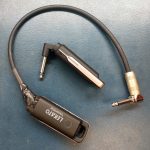
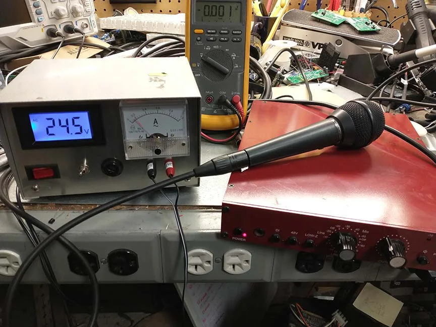
It all worked the way it was supposed to on the first try. I was able to put it to use the day I completed it because someone asked me to fix an outboard mic preamp, but they didn’t give me it’s power supply. The preamp needed 24VAC, so my new AC power supply was just what I needed to help me fix it!
This was a pretty straightforward project. I enjoyed making this tool and adding to my bench. It will be used regularly for a variety of jobs.