- Your cart is empty
- Continue Shopping
Boss Pedal Switch Auto-On or Off Mod
Solving a personal pet peeve by controlling the bypass logic of Boss pedals when they are powered on.
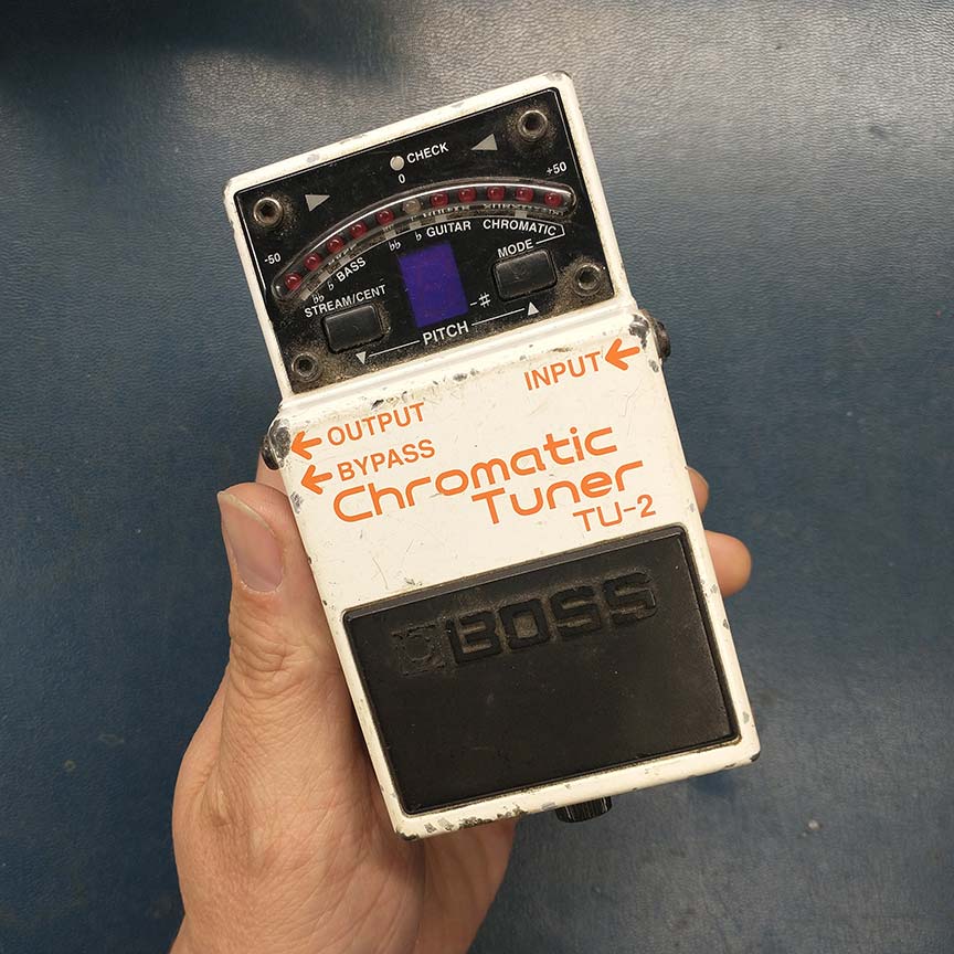
I know it might sound picky, but one of the things that is really annoying to me is that Boss pedals are not consistent in their bypass logic when you power them on. On one of my pedal boards (the one I happen to be using the most right now), I have a Boss TU-2 tuner pedal and a Boss DD-3 digital delay pedal. I normally always keep my tuner on 100% of the time (because I use my VPM-1’s tuner output) and I almost always want my DD-3 off when I start playing. Annoyingly, every time I power these pedals on, the TU-2 is in the off state and the DD-3 is in the on state. So the bypass logic of these pedals upon power on is backwards from what I want and expect. In searching around the internet for any answers to these issues I discovered this forum (Boss pedals, way to defeat auto-on when turning power on? – Effects and Processors – Harmony Central, Boss DD-7 Question: Pedal Automatically Powers On | TalkBass.com, ) in which much the same sentiment was expressed. I know a lot of people on the forums were saying “get over it,” but that is not my nature…I recognize a problem here and I want to solve it!
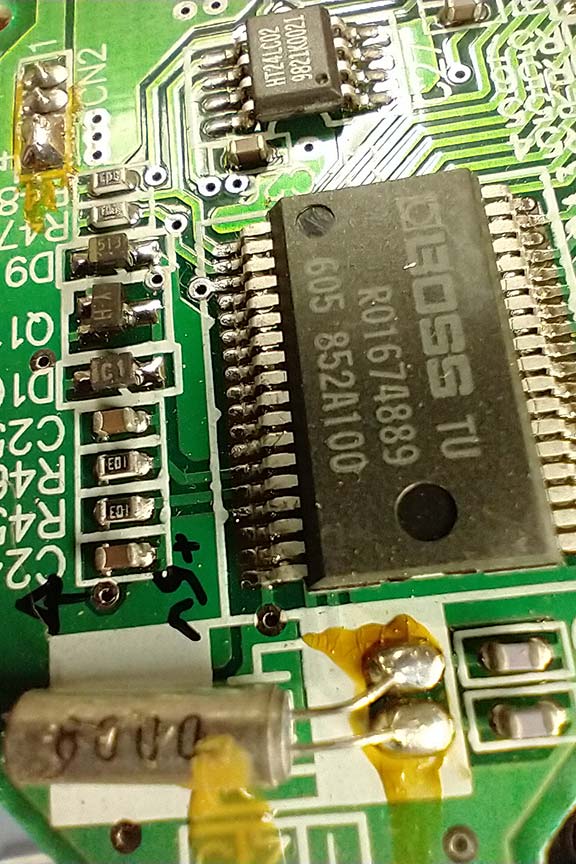
The bypass switching logic on Boss pedals (depending on the model) use either a toggling “flip flop” circuit or a microcontroller that does the same thing with less electronic components. The TU-2 happens to use a microcontroller to handle all the switching (and most everything else for that matter). On these types of pedals, the footswitch is just an actuator that presses a single pole single throw momentary switch. One pin of the momentary switch is connected to ground and the other pin is connected to the microcontroller. When the switch is pressed, the pin on the microcontroller is held low (connected to ground), and then another microcontroller pin (we’ll call the “output pin”) latches high until the switch pin is held low again, at which time the microcontroller output pin latches low. This output pin just alters states (high or low) each time the footswitch is pressed, which we call “flip-flopping”. The output pin of the microcontroller is connected to some transistors (mostly FETs) in the circuit that act as switches and re-route the audio signal through the effect circuitry or to the pedal’s output jack depending on which state the bypass logic is currently residing.
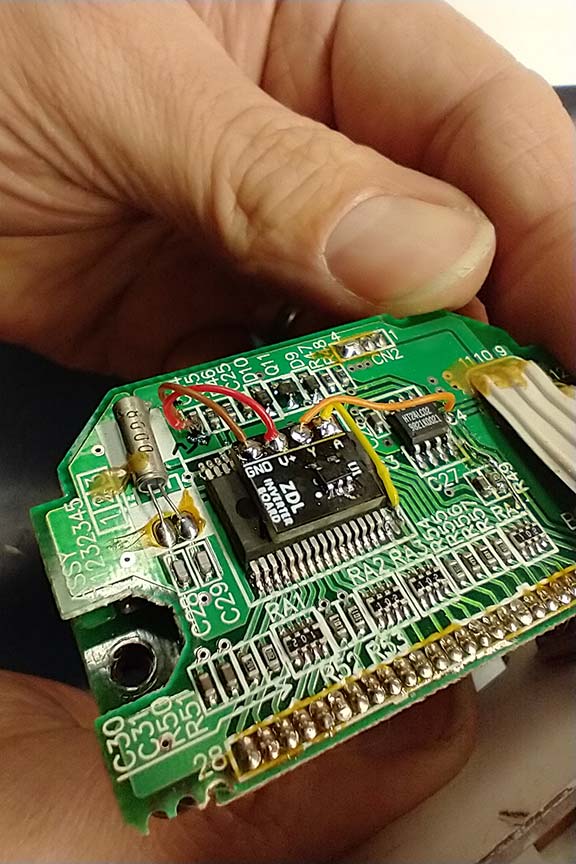
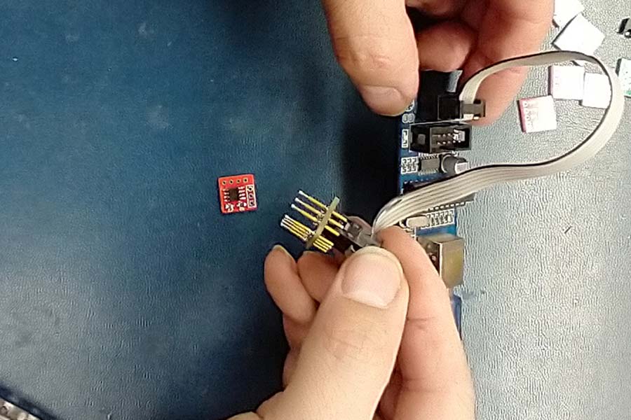
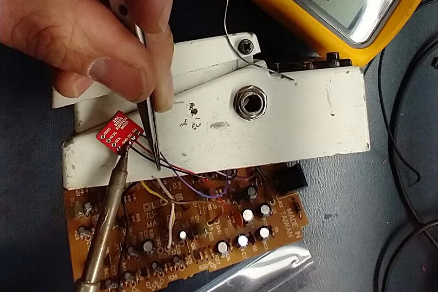
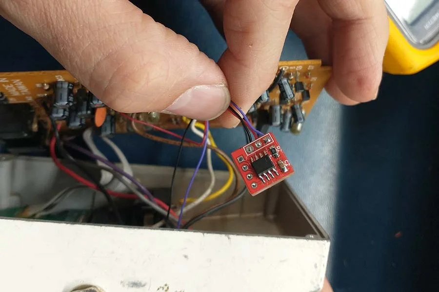
I happen to have some tiny single inverter circuit board modules that I made for a different project a while ago.
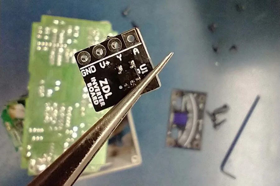
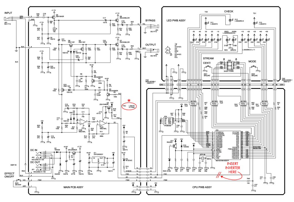
Inverters are very useful devices that have an input pin and an output pin. When the input signal is high, the output signal is low, and vice versa. I thought I could use these to accomplish my goal of turning the tuner on each time it’s powered on. I just needed to put one of these inverters in the path of the output pin on the microcontroller to reverse its logic signal. I studied the schematic and determined where the inverter needed to go. Then I studied the circuit board layout to determine what trace needed to be cut so that the inverter could be installed in line (in series) with the trace. The TU-2 service manual (which was relatively easy to find online) was very helpful with these tasks, because it included both the schematic and circuit board layout.
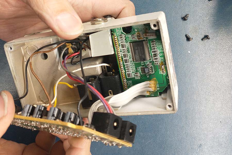
I was able to make the modifications to the circuit board and install the inverter. I also had to find a 5 volt power rail and ground to hook up to the inverter board module, which wasn’t difficult.
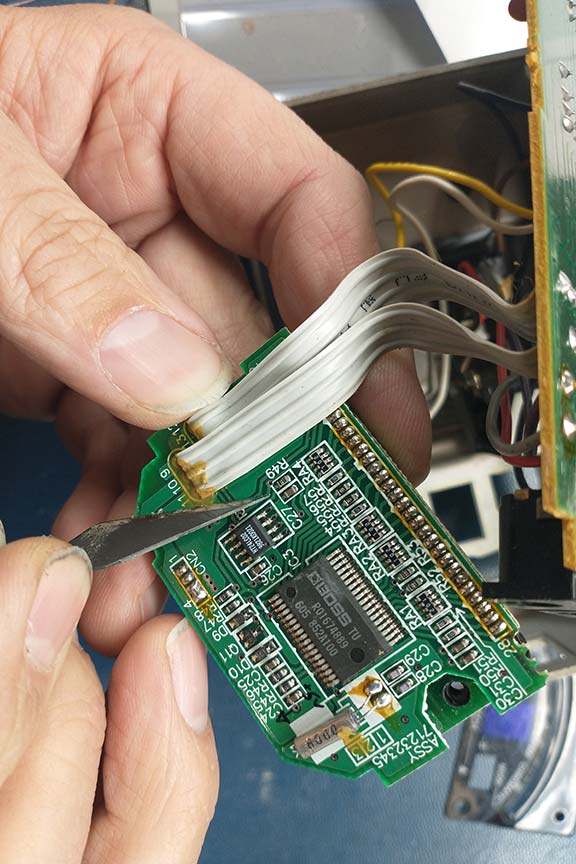
When I tested my mod out, the pedal switching logic worked as expected. When the pedal powered on the microcontroller’s output pin logic was reversed allowing the audio signal to be routed through the pedal circuitry as intended. The only problem was that the LEDs on the top of the pedal, including all the LEDs that show the tuning information, were not on the same logic phase as the now inverted output pin. So now the pedal was basically useless because the when the audio signal was able to reach the tuning detection circuitry, the LEDs were off and I couldn’t see any information about how out-of-tune my guitar was, and vice versa. I completely forgot that the other pedal functions controlled by the other microcontroller pins were still operating on the original logic. If I was going to use inverters to solve this problem, I would at least need an inverter on every microcontroller pin connected to an LED, and there is a lot of them on this pedal. So it’s back to the drawing board for me.
Like I always say, if all else fails, use a brute force technique. In this case, I decided to attack the problem at a much higher level…by simulating a foot press on the footswitch. When someone turns on this pedal, the output pin on the microcontroller is held low. So all I would need to do is hold that pin low for a bit and the microcontroller would think the footswitch was pressed. The easiest way to do this is to use a different microcontroller. Every time the pedal and new microcontroller are powered on, I could have its output pin stay high while the pedal boots up (for about 2 seconds on this pedal), and then simulate a foot press by going low for a split second (let’s say ¼ of a second), and then go back high again…and do nothing else the rest of the time it’s on.
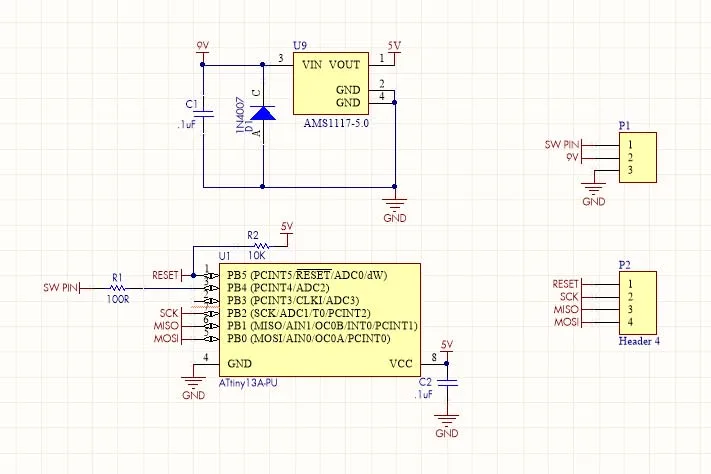
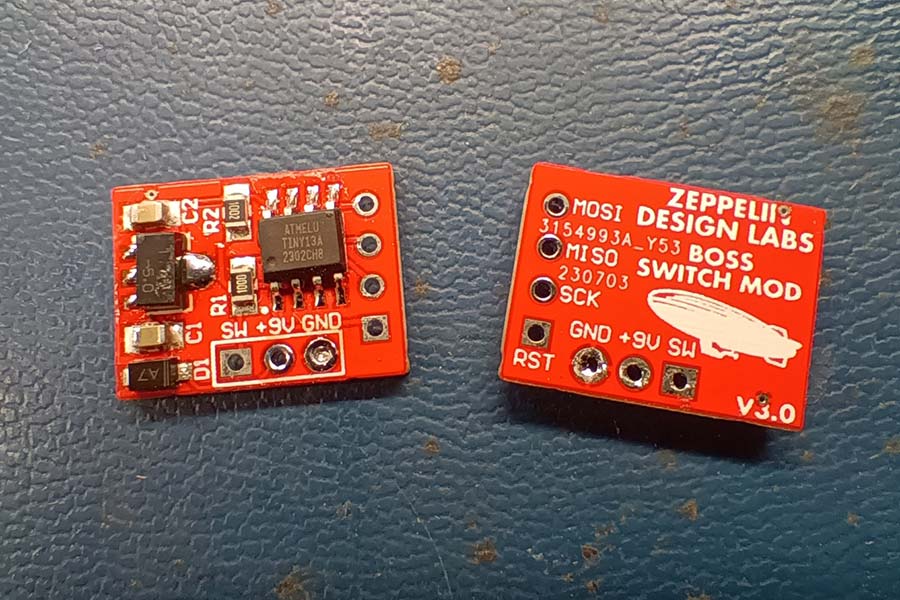
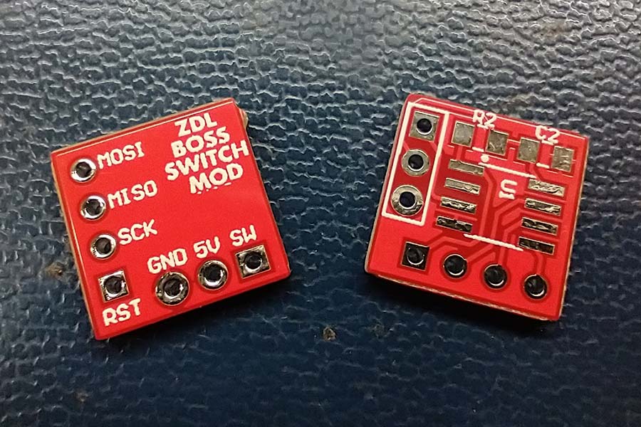
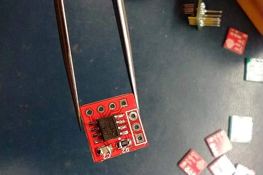
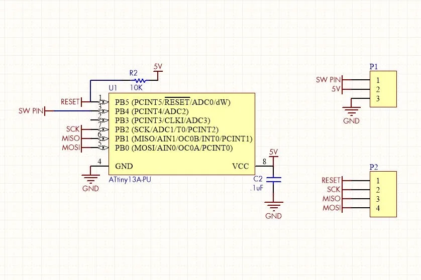
The model of microcontroller I decided to use is the ATtiny13a, made by Atmel. I happen to have a bunch of these little chips in our lab. They are small and easy to use. I designed a small circuit board that would easily fit inside the pedal chassis, complete with pads for flashing (or programming) the microcontroller.
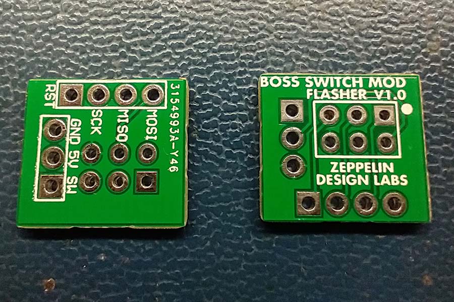
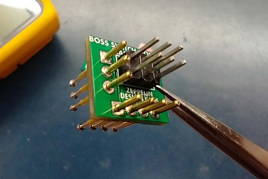
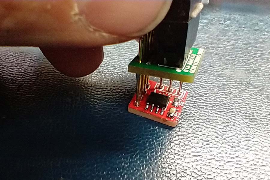
To help flash the microcontroller, I also designed different a circuit board. This flash board had a 6 pin header, which is commonly used for in-system programming (in this case I’ll use a USBTiny programmer). I also added several holes to the circuit board large enough to fit pogo pins. Pogo pins are spring loaded pins that are used to temporarily electrically connect two circuit boards together, as in this application.
I wrote the code in Arduino and flashed the microcontroller using AVRDude. Here’s the very simple Arduino code:
/*
BOSS AUTO SWITCH MOD
by Brach
Toggles the state of a Boss pedal once the power is applied.
Designed for use with Attiny13 uC, on hardware designed by Brach / Zeppelin Design Labs ("BOSS SWITCH MOD" board).
*/
const int SWPIN = 4; //
// the setup function runs once when you press reset or power the board
void setup() {
pinMode(SWPIN, OUTPUT); // initialize digital pin SWPIN as an output.
digitalWrite(SWPIN, HIGH); // write pin high after power is applied, while pedal boots up
delay(2000); // wait for 2 seconds
digitalWrite(SWPIN, LOW); // emulate foot switch being pressed down
delay(250); // wait for 250mS
digitalWrite(SWPIN, HIGH); // write high again (releasing the foot switch)
}
void loop() {
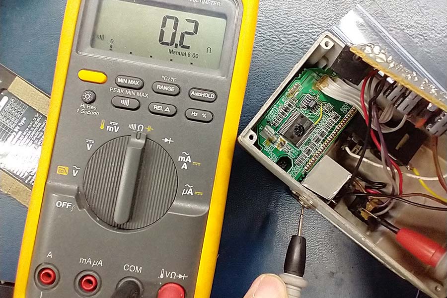
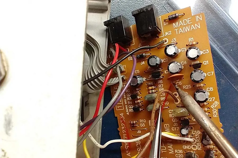
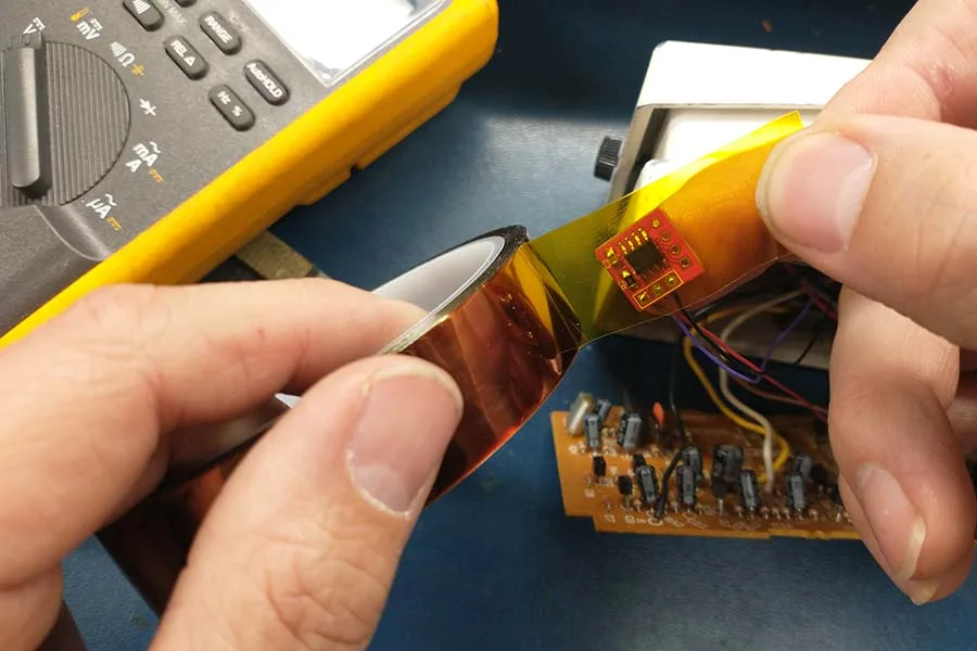
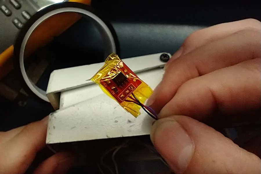
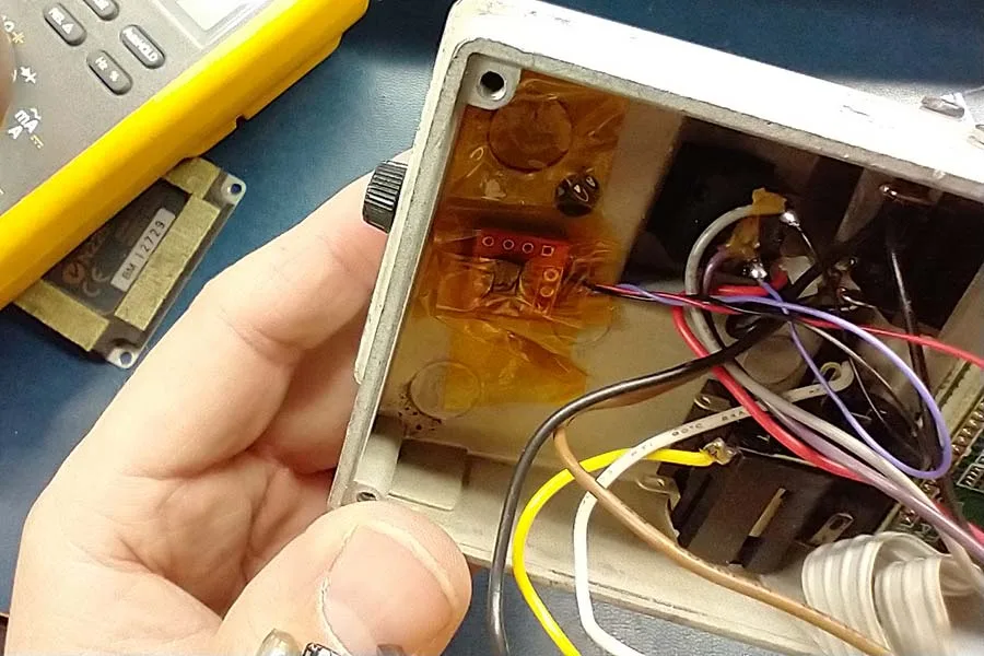
} // do nothing the rest of the time the power is onThis mod was very easy to install, much easier than my original idea with the inverter module. This mod only has three wires that need to be attached to the board: the switch wire, 5 volt wire, and the ground wire. I soldered the switch wire and the ground wire to their proper pins on the pedal’s momentary switch. It helped to use my continuity tester to find out which pin on the switch was the ground pin (it was connected to the barrel of the input or output jacks). I looked at the schematic to find which components were connected to the 5 volt rail. I found a capacitor directly after the 5 volt regulator that was easy to solder to on the component side of the board. I wrapped the circuit board up in Kapton tape to keep it from shorting out against anything. I also taped the board to the bottom side of the chassis to keep it from rattling around.
It worked great! The two second delay before the switch pin goes low is just the right amount of time for the TU-2 to finish booting…and then the pedal turns on, as expected. For other pedals the code could be adjusted to extend or reduce the boot-up time delay. For me, I don’t care how long the delay time is, as long as I don’t have to manually turn on or off a bunch of pedals before I can start playing.

This mod is relatively simple and easy to implement and also easy to remove if the stock circuitry is desired. This mod should also be able to work with any pedal with a similar switching scheme as the Boss pedals (weather the switching was done with a digital microcontroller or with an analog flip flop circuit) …that is, toggling the switch logic when a normally high switch pin is held low. This is the way most pedal “soft switches” work. The pedals that I design, including the Quaverato, operate this way…but of course, the Quaverato has a built-in function allowing the user to choose what switch logic (either bypassed or engaged) they want upon power up. Apparently, this annoying issue with Boss pedals has been on my mind for several years, even back when I designed the Quaverato…I’m glad I finally have a solution!
Edit…
Since I originally wrote this blog, I redesigned this circuit and board to include a 5V regulator, as well as a reverse protection diode. This way, I don’t have to find the circuit’s 5V rail (assuming the pedal even has one) to power this circuit; I just need to run the power wire (previously called the “5V wire”) to the pedal’s 9V power jack. It’s even simpler to install now, which is good because I’ve been modding a lot of my Boss pedals with this board.