- Your cart is empty
- Continue Shopping
Home › Forums › Quaverato Forum › Quaverato FAQ & Support › EVERYTHING works but Bypass LED
- This topic has 16 replies, 2 voices, and was last updated 7 years, 3 months ago by
brach.
-
AuthorPosts
-
Seth N Peacock
GuestThe effect and every part of it are working fine except for the bypass LED does not come on. So far in my trouble shooting ive confirmed:
Bypass switch works, switches the effect on and off.
No continuity from the – bypass LED to R11. No continuity from the + bypass LED to pin 6 on the IC. Thought this was the problem so I ran hookup wire from R11 straight to the led anode and and from pin 6 to the cathode. No cigar.
LED has been tested, and when i run the cathode wire to pin 5 it pulses in time with the tap tempo led.
There is 4v of power coming out of pin 6, unchanged by clicking the bypass switch.I’ve got 4 questions now that I’d like to find out, and of course fix the pedal along the way.
1 why wont pin 6 light up my test LED pulse when it shows theres 4v there?
2 Why wont the bypass switch turn on and off the voltage to pin 6? It turns the pedal on and off just fine.
3 why were there no connections to the LED socket on the circuit board?
4 why does pin 6 measure at 4v instead of 5v?Guestalso, i am checking directly on the ic, not the socket/solder side.
Secondary question: I broke off pin 1 taking out the ic. Do i need new chip entirely or can i just run a piece of hookup wire from the pin stub on the ic to the respective solder pad on the pcb? I’m assuming pin 1 being inoperational isnt my problem because with absolutely nothing else considered, I’m getting 4v at that pin and yet the LED wont light up while touching it.
brach
ParticipantThe good news is everything else is working fine, so this LED should be too hard to fix…in theory.
First of all, R11 should be hooked up to the LED cathode (the round pad), not anode (the square pad); and the LED anode, not cathode, should be hooked up the the U1 pin 6….please note the schematic. Reverse your hookup wires and see if that fixes the problem.
If not, re-seat the microcontroller in it’s socket to make sure there’s not something wrong with one of the pin connections.
There is a chance that the LED could be in backwards. Using your diode tester on your multimeter, with the red lead on the square pad and the black lead on the round pad you should get around 1.7V across the red LED (and around 1.8V on the green LED).
You can just run a jumper from pin 1 of the microcontroller to it’s pad. Pin 1 is the reset pin so it shouldn’t matter for this LED problem…but you do need to hook it up to keep your pedal from resetting every time pin 1 drifts low.
Let me know what you find with the LED.
-BrachGuestWhoops, yeah I had it hooked up right just used the wrong terms. I tried the LED both ways, no luck. There’s no voltage going to the pads (like I said they dont seem to be connected to anything) but I measure DC 4v with the red directly on pin 6 and the black on ground. Still, the LED (which has been tested) doesnt work when placed between pin 6 and the resistor going to ground.
ParticipantI’m confused…Are you getting 4v (or any voltage drop) across the red LED?
Are you getting continuity from the solder joint of pin 6 on the microcontroller socket to the LED?
Did you re-seat the microcontroller in it’s socket?
Did you test the polarity of the LED, as it’s installed?
While you are answering these questions please also check (and even re-flow) the solder joints on the microcontroller…specifically looking for tiny bridges around pin 6.
-BrachGuestYes, I have checked all of that. no voltage drop across the led, but I am getting 4v across pin 6 to ground. However, I think i just may have found the issue, but im not sure how to solve it. pin 6 is continuous with ground but only when the pedal is powered up. So are pins 13 and 14 which I saw are the relay pins. Also, I finally tried running a guitar through it for the first time since i started troubleshooting and now the pedal doesnt work anymore. just clean signal. Does this mean theres a short somewhere? Where could it be to mess up pins 6 13 and 14?
ParticipantPins 13 and 14 usually measure only about .5 ohms to ground because they are across the relay’s coils, so it may seem that they are shorted to ground but they are not actually. I’m pretty sure that is what you are discovering here.
Because pin 6 is programmed to low when the LED is not on, it should measure a very low resistance to ground. As with the other pins, it may seem like it’s shorted to ground but it’s probably not.First answer this: Are you sure that neither side of the LED is making connection to the parts of the circuit it is supposed to connect to? Is either pin of the LED connected to R11 or pin 6 of the IC? You mentioned this in your first post, but it seems unlikely that both pins aren’t connected to anything unless your board has been damaged somehow.
I’m curious about the socket…sometimes they don’t make good connection to the IC pins. (1) What is the resistance between the the solder joint of pin 6 on the socket and pin 6 of the IC? (2) Also, does the 4V on the IC pin change when you press the bypass switch? (3) Does the voltage on the pin change with the LED out of the circuit? I’m wondering if the LED has been damaged and is only dropping 1 volt, instead of the 2 volts it needs to light up.
Please answer these 3 questions directly.
As far as your pedal not working anymore, it sounds like there may be some opens or shorts on your board somewhere. It would be helpful to me if I could see your board. If you could send me some detailed, in focus photos of both sides of your board, that would give me a better understanding of what might be wrong.
-BrachGuestAfter extensive fiddling I got it to show continuity from the square pad for the LED to pin 6; I mustve just destroyed the solder pads when I desoldered the original LED. I havent gotten the other pad to show connection to the resistor yet but I’m sure the same thing happened there.
1) It shows between 0 and 0.002, and the continuity function of my meter says its continuous.
2) 4V across the LED every time I press the bypass switch. I just realized that one of the toggles makes it momentary so when I was done with all the testing I pushed the toggle the other way and tried everything again to make sure it was in the right position.
3) Desoldered the hookup wires connecting the LED to pin 6 and the resistor; same result. Just tested the LED again by touching one wire to ground and the other to Pin 5, it strobed in time with the tap tempo LED.(Yes, I’m aware the tap tempo switch isnt connected. It kept coming off as I turned the board from front to back so I figured I’d just solder it a final time once I fix it).
ParticipantThanks so much for the photos. That’s very helpful.
I notice that you do have a lot of rough looking solder joints. Most likely, the messiness of your board is causing these problems you are experiencing. You might want to try to clean up the joints with lots of solder on them…they will have a tendency to become oxidized and crack. There also seem to be a lot of tiny pieces of solder sticking out from many of the pads…these can short to the ground plane or other pads very easily…please clean those up by removing much of the extra solder on most of the pads. The microcontroller has a lot of burnt flux around many of the pins that you have been soldering to a lot (especially around pin 6)…try to remove this with some high percentage rubbing alcohol or acetone on a q-tip. It actually can become somewhat conductive. In general, try to use less solder on each joint…it’s much easier to control if you use solder that is very thin in diameter (I use .8mm wide solder). Also, it’s usually much better to use much thinner wire to run jumpers so it’s easier to control and you don’t accidentally short pins together with the thicker wire.
There is a large blob of solder on one of the pins of R11 that I am concerned may be shorting to ground…try to fix that.
There is a via right below the “R” of the word “RED” next to the bypass led. Make sure that nothing is shorted to that via from the midi in header.
For questions 2, I was asking about what is happening on pin 6 of the microcontroller when you press the bypass switch (not the LED). Make sure the bypass LED pins aren’t shorted before you check this (just in case they are connected).
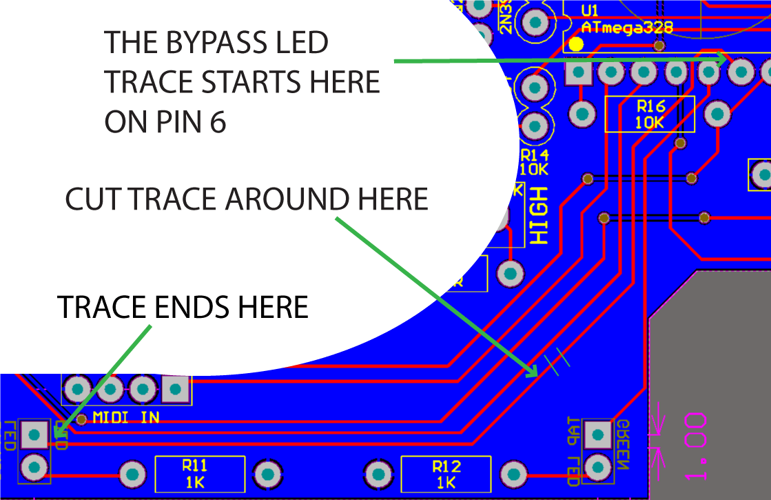
The goal is to get the microcontroller cleaned up enough so that we get 5v on pin 6. If you are confident in your jumper running ability, it may help to cut the trace coming from pin 6 to ensure that nothing around the LED is causing this 4V issue.
-BrachGuestCleaned everything up, touched all the questionable solder joints to make sure they werent cold. Still no luck. I thought that may have been what you meant with question 2 so I had already checked that too just in case. After cleaning I Got a reading of 5V a couple times and got excited for a second, but I think I may have slipped over to pin 7. Now its still at 4v and wont change with the bypass switch.also, thanks for the advice on the solder, the stuff im using is definitely too thick.
I checked the bypass switch again, making sure the contacts were only continuous when the switch was pressed.
What did you mean by cut the trace to pin 6?
GuestTheres some new pictures to make sure I cleaned everything up enough.
ParticipantThat looks much better. Good job. It will be much easier to track down problems now because we can probably trust that there are no (or very few) issues with assembly…and they will be easier to fix when they do come up.
Is the tremolo audio functioning yet? I just want to double check that the bypass switch is working properly before we do anything destructive like cut the LED trace. It does/did switch the relay, didn’t it? Also, when you measure the voltages, what point are you using for ground?…a good ground point is pin 1 of the input or output jack, which is the shield tab…it is the one closest to the edge of the board. It might also be good to double check your voltages before you cut the trace.
To proceed with cutting the trace (which isn’t that big of deal because you can always re-run your jumper to the LED from pin 6)…You can see in the picture were the trace from pin 6 comes from and where it goes. Use your xacto knife and cut a small section out of this trace…cut two lines across the trace 1-3mm apart and then peel up the cut trace in between the lines. Make sure you don’t accidentally cut the wrong trace.
Good luck!
-BrachGuestUnfortunately audio is not working. It was originally but at some point in my troubleshooting process I must have messed it up. The switch itself is working, or at least is making a connection between the solder points on the board when its depressed. Where can I check to make sure its connected to the relay properly? I was using the “ground” labelled hole that is connected to the depth pot. When I get home tonight I’ll cut the trace and double check the voltages with the ground you described.
By the way, thanks so much for all the help and sticking with me thus far.
ParticipantThere is no hold labeled ground that is connected to the depth pot. There is a hole labeled “GND” on one corner of the board, is that what you are talking about?
You’ll know the relay is working because you’ll hear it click when you press the bypass switch. If it is not working then that may be your problem (or at least one problem). You’ll need to double check your solder joints (especially look for bridges) where the wires solder to the board from the switch and on the switch itself. Also check the solder joints around the relay.
-BrachGuestSorry yeah, thats what I meant. GND stands for ground doesnt it? Its the one connected to a ring that you slip around one of the pots, I thought it was depth but I’m not 100%.
Will the relay click whether or not the pedal is powered up? -
AuthorPosts