- Your cart is empty
- Continue Shopping
Home › Forums › Quaverato Forum › Quaverato FAQ & Support › No Effect
- This topic has 31 replies, 2 voices, and was last updated 7 years, 3 months ago by
brach.
-
AuthorPosts
-
jrg320
ParticipantAlright, I have poked and prodded each component, I have gently nudged and moved each pot trying to find anything that might be shorting. The only difference I get is when I touch certain legs on the ICs there is extra static. I have not been able to get any effect or even dry sound when the effect is engaged. I am beating myself around the head, because I can imagine it is a very simple thing that I am missing.
brach
ParticipantHearing static is a good thing. It means that the output circuitry is working. Actually the pedal was working at one time so you should be able to get it working again…this is why i think something is shorted or opened (as in a solder joint that isn’t making good connection.)
Let’s start at the beginning of the signal path…Can you hear any noise when you touch the relay lead closest to the edge of the board, on the side of the relay closest to the power led?…this is attached to the input of the effect circuit (make sure the volume pot turned up when you do this). You may even want to touch your guitar cable to this relay lead so you can inject some sort of signal into it (you’ll have to find another cable to plug into the input jack so the pedal will turn on).
You can go through the circuit this way, following the signal path in the schematic, touching various leads in the circuit that are next in the signal path. One bottleneck to look for is the LDRs. Are you hearing noise when you touch a point before the LDRs in the circuit…or just after?
Let me know what you find.
-BrachParticipantWhen I touch the leads relay lead closest to the edge of the board on the side of the power LED, I get a slight static. I also get a high-pitched squeal when I touch the legs of the trim pots on the input-side of the LDR.
One other place I get sound is when I touch leg 2 of the volume pot with the lead of C1 at the same time. I get full bypass tone and the effect stays on (relay does not switch off.) None of the other pots do anything, but I can drop the volume of the input signal with the volume pot (full volume remains at unity.)ParticipantWhat do you mean the relay does not switch off?…Is is stuck in one position or the other? What did you mean when you said you get a “full bypass tone and the effect stays on”? Does the signal run through the effect circuitry or is it bypassed through the pedal? I’m confused.
So for good measure let’s double check to make sure the relay is working…
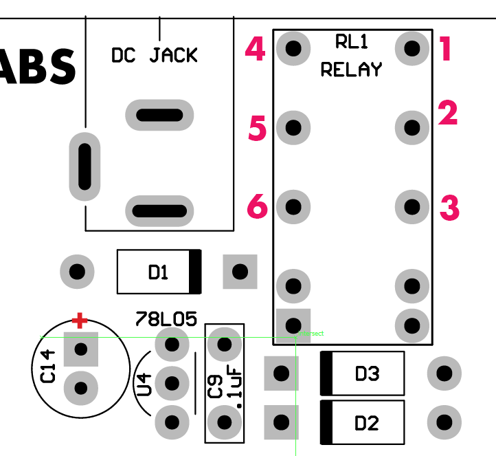
When the effect is on, as in when the red led by the bypass footswtich is on and you expect to hear the tremolo sound through the pedal, pins 1 and 3 of the relay should be connected and pins 4 and should be connected. Test this with your continuity tester.
When the effect is off and the signal is just bypassed through your pedal pins 3 and 2 should be connected and pins 6 and 5 should be connected. Please test these and let me know what you find.
If the relay isn’t working properly….
Try to re-seat your microcontroller in it’s socket. We need to make sure the pins that control the relay are making good connection. Be careful when you pull it out not to bend any leads.If the relay appears to be working properly then…
With the pcb out of the chassis, make sure each of the pots are bent slightly upward away from the board to ensure none of other component’s leads are touching the back of the pots.
With the depth knob set fully counter clockwise, what happens when you touch TP3 and/or TP1? Do you hear any noise? TP3 and 1 are directly before the LDRs.
Please be specific about which trim pot were you touching…VR8, 9, or 10?Let me know what you find.
-BrachParticipantI meant when I bridge between the second lug of the volume pot and the capacitor the bypass LED stays on by my bypass signal is coming through as well without any tremolo effect. It appears to be running through the circuit, because the volume pot will effect the volume of the bypass signal. I don’t know if this is relevant at all, just something I found was happening.
The relay appears to be working, continuity across the pins you described.
Nothing happens when I touch TP3 or TP1.
The noise comes when I touch the leads of VR10 and R4 and R5.
ParticipantOk, thanks for the clarification.
Please don’t bridge C1 with the volume pot…it’s not helpful because as you can see from the schematic they are on opposite sides of the circuit.
If the effect circuit is bypassed (the red led by the bypass footswitch is off) the volume pot should not be controlling the signal at all. The volume pot should only be controlling the signal when the red led is on. Is this happening with your pedal?
Is nothing happening when you touch TP3 or 1, even when the effect is engaged and the depth knob is fully counter-clockwise?…you shouldn’t hear anything when the effect is bypassed. What about when you touch TP 4 and 2?…theoretically, you should hear something with TP4 and 2. Try touching the test points with something metal…I used a pair of tweezers to touch the test points on the Quaverato on my desk and it made noise on each of them (TP1-4)…but only when the effect was engaged.
VR10 is after the LDR’s so you should hear something from that when the effect is engaged.
-BrachParticipantI have probed TP1-TP4 with tweezers with the effect engaged, depth turned all the way counter clockwise. I get no sound at all from them.
ParticipantDo you get any sound when you touch pin 1 of the relay with your metal tweezers? What about R4 and R5?
ParticipantRelay pin 1, R4 and R5 will all make sound static noise.
ParticipantThis probably means that the solder jumpers on both the high and low sides are not making connection. Use some small gauge wire and run some jumpers as in the picture…

This bypasses JP2 and JP4. But you also need to make sure that JP3 and JP1 are soldered correctly. You can see if JP1 and JP3 are connected properly if both the green pads are connected and both the blue pads are connected…use your continuity tester.
If they are not connected, to fix them you can get a tiny bare wire (like a short component lead) and solder that to the 2 pads of the solder jumper…if that helps to get the connection made.
-BrachParticipantBrach! These seems to have done most of the trick! I jumpered R4 to TP4 and R5 to TP2. I am now getting tremolo and all the knobs seem to be doing something. I do not, however, seem to be getting the “Harmonic” effect.
Now, I don’t seem to have a good connection at JP3. I believe my pads are burned past the point of soldering anything to them. When I tried to attach a small piece of wire, it didn’t have anything to adhere to.
https://drive.google.com/file/d/1enTMnNzErKcSwl3Mak0h9ykUjPVLoGU1/view?usp=sharingParticipantBrach! These seems to have done most of the trick! I jumpered R4 to TP4 and R5 to TP2. I am now getting tremolo and all the knobs seem to be doing something. I do not, however, seem to be getting the “Harmonic” effect.
Now, I don’t seem to have a good connection at JP3. I believe my pads are burned past the point of soldering anything to them. When I tried to attach a small piece of wire, it didn’t have anything to adhere to.https://drive.google.com/file/d/1enTMnNzErKcSwl3Mak0h9ykUjPVLoGU1/view?usp=sharing
ParticipantThat’s great!
In reviewing the previous picture I sent you, I realized I got the jumpers backwards…TP4 should go to R5 and TP2 should go to R4. Sorry! That may be causing your harmonic mix knob problem.
If that doesn’t fix the harmonic mix knob issue then it’s probably because JP3 is damaged and signal isn’t getting through. You can run a small jumper across the blue pads in the previous picture (maybe try this on the solder side of the board if the top side is too cluttered with components). That will bypass JP3.
Good luck!
-BrachParticipantAlright. I swapped around the bridges and bridged the IC to the LDR. Everything seems to be working well now! I do notice it is a much darker tone than my bypassed clean tone. Will I need to re-calibrate the trim pots, or is there another issue?
ParticipantGood! I’m glad it’s up and working now.
Yes, you will need to re-calibrate the high and low trim pots. The given values for those were just starting points. Now you need to tweak them to the tone you like.
Good luck.
-Brach -
AuthorPosts