- Your cart is empty
- Continue Shopping
Forum Replies Created
Viewing 12 posts - 1 through 12 (of 12 total)
-
AuthorPosts
-
aleach07
ParticipantBrach,
I received my replacement microcontroller today — popped it in and the pedal works perfectly! Functions great, sounds fantastic!Thanks again for all of your support. I certainly learned a lot about how this pedal works!
Cheers,
AndrewParticipantBrach,
I don’t have a USB tiny, but looking thru the documentation and driver info it looks like it’s PC only? Any way I can re-flash the micro w/ a Mac? I don’t have a PC anymore unfortunately. I’m also happy to just order a new micro at this point and mess w/ the old one some other time.Thanks,
AndrewParticipantDan,
At this point I would still recommend this pedal/kit. Although I haven’t gotten mine functioning yet, the support from brach has been excellent. Sometimes components fail. I’d have certainly been bummed if the response was “build at your own risk, sorry!” but it’s been far from that. The circuit isn’t that complicated, the documentation is excellent, and given your experience, I doubt you’ll have a problem assembling this pedal.Thanks,
AndrewParticipantSome additional data from stuff I’ve checked:
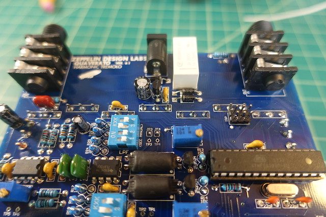
VR1-6 voltage divider network as analog inputs to micro check out okay, measuring 0 to 5V input to micro itself. Meter placed on the shoulder (?) of the pin itself at the chip, example shown below). So I know each pot’s wiper is adjusting 0 to 5V smoothly and independently and the micro is seeing that voltage — measurement location rules out opens or shorts from pot all the way thru board, micro socket, to micro. Is it possible there is an internal short or break in the analog input section of the ATmega chip itself? I keep going back to something wrong with the micro probably because it’s not something I can check myself. Will prob just order a new one anyways simply to rule it out for my own sanity.
Example of where I’m measuring I/O voltage for micro when troubleshooting:

Other stuff:
Vref = Vcc = 5V, stable
P2 pins checked, 5V on pin 2, GND on pin 6, pins 1,3,4,5, continuity back to corresponding pins on micro.
P3 pins checked, 5V on pin 3, GND on 2 and 4, 1 open, continuity back to MIDI IN pin on microPhase switch works — at times when getting trem effect, can hear the difference between normal and harm trem.
Mode switch works — momentary/latched modes check out.
Footswitches open when not depressed, closed when depressed only.Y1 probably working since when the effect does work, the tempo is steady. C5/C6 verified correct values.
Variable resistors & gain set per build manual.
ParticipantNo worries!
Yes, the board behaves the same way whether it’s mounted in the chassis or the way it’s shown in pictures. Definitely no shorts between the pot cases and the board below.
Thanks,
AndrewParticipantStill looking into this. Is there a way to troubleshoot Y1 other than visual inspection of the solder joints and verification of C5/C6 values?
Thanks,
AndrewParticipantHere are the pics (with paper removed / pots slightly bent back to reveal board underneath).


Thanks,
AndrewParticipantRemoved and re-seated the micro — same symptoms.
Aref is 4.9V, seems stable. Same 4.9 at U4.
Same symptoms as when I was messing with the presets, altho I wasn’t able to reset all 6 presets (mentioned previously where all position of pot resulted in preset 6 writing or no preset writing).
Sweeping the pots doesn’t change anything.
Thanks,
AndrewParticipantHmm, weird result.
Performed the preset re-write per the MIDI manual. At positions corresponding with presets 1, 3, 4, and 6, I get rapid flashing followed by 6 blinks, which according to the MIDI manual, correspond to preset #6. Positions corresponding with presets 2 and 5 I get rapid flashing followed by no blinks at all. Double checked that the voltage reading at the input to the micro was 0, 1V, 2V, 3V, 4V, and 5V at each position of the multiplier pot. Don’t know why 4 out of 6 positions wrote to preset 6 while the other 2 apparently didn’t write at all.
Any way I can order just a replacement microcontroller?
Thanks,
AndrewParticipantOk cool, definitely stoked to try this out when I get home tonight! Not being familiar with the way the Quav utilizes the ATMega micro (I have messed around w/ Arduino before tho), I’m running out of other hardware to check and recheck.
Thanks again for such a detailed response Brach!
For my own curiosity:
I read thru the MIDI-mod manual. So when (re)setting the presets, you’re basically setting each preset to whatever the pots are set to when performing each preset write? We just need to have real/valid values in the registers? Are these presets used for anything if not running the MIDI mod?When sweeping all pots full clockwise, then counter-clockwise, the the micro looking for anything particular under these conditions or doing anything w/ that information? i.e. IF [all VR inputs 0V] do this, IF [all pots 5V] do that).
Thanks again,
AndrewParticipantBrach,
Thanks so much for the detailed response!Update:
Getting tap LED flash sequence 2-3-6 when performing the start-up hold above. This matches up w/ the slip of paper that came w/ the unit, s/w ver 2.3.6. Good to go I guess.
I checked Y1, C5, and C6 first. Continuity or open where it’s supposed to be against the schematic (Y1 should read open when unit is powered off I assume). Replaced C5 and C6 just in case and remeasured everything.
Checked each pot again, checked voltage across wiper to ground at various positions of the pot’s sweep, verified getting the same voltage reading at their respective pins on the microcontroller (verified at the actual pin on the chip, not just the solder point of IC socket/PCB).
Went back and checked correct component placement again.
Here’s a more detailed set of symptoms:
Power unit up, bypass LED off, tap LED on solid, effect is off, clean sound thru amp. I would assume the tap LEP should be blinking at the rate corresponding to the position of the Rate pot at this point.
Click bypass switch, bypass LED turns on, tap LED still solid, unit still passes clean sound.
Move the rate pot around a little, tap LED shuts off, unit no longer passes sound.
Click Tap switch a couple of times, unit starts passing trem-ed sound and Tap LED shows tapped tempo.
Move Depth pot around, jittery trem-ed pulsed not in time w/ tempo, unit returns to correct trem-ed pulses while not moving Depth pot around.
Move Multiplier pot around, tempo jumps to 4:1, stays there until I tap a new tempo in, which is now pulsing at 2:1 ratio regardless of Multiplier pot position.
Moving Shape pot around does the same as moving Depth around.
Spacing pot works fine (woo!)
Harmonic mix works fine but does cause some jittery pulses during pot sweep.
I have to this there is something wrong w/ 5V voltage divider network forming the inputs for VR1 thru VR6, but they measure fine w/ my meter and I’m not sure how the tap tempo would work and/or be affected by this anyways.
Will probably start pulling pots off and replacing w/ 100k resistors to max/min out certain parameters one at a time to see if I have a weird pot or something that’s causing voltage spikes or something. Or replace Y1. Or buy a pre-made unit and give up on this one!
Truly stumped.
ParticipantI’ve checked the circuit against the schematic in the build instructions:
The VR1-VR6 voltage dividers / analog inputs read 0 to 5V independently based on pot position.
VCC = 4.9 volts
Continuity across U1 ground, PCB ground, pot ground lugs, etc.
Is there a way I can check if U1 is functioning properly?
-
AuthorPosts
Viewing 12 posts - 1 through 12 (of 12 total)