- Your cart is empty
- Continue Shopping
Forum Replies Created
-
AuthorPosts
-
brach
ParticipantAndrew,
I’m so sorry…I don’t know how i missed that you posted those photos. That gives me a good visual of your board. I’m curious if the board behaves in the same weird way when it’s out of the chassis, and the pots are pulled up a bit (away from the board) as in the photos. I want to see if something might be making a short to the board, like the pots or the chassis. It seems like some of the leads under the pots are long enough to potentially poke through the paper. Let me know about that.
It’s not easy to test the crystal with out an oscilloscope, but if the green led is blinking consistently then it should be working alright.
-BrachParticipantIan Erik,
I’m sorry to hear about your Macchiato troubles. The guys at Koma should be able to help you. The first step is to re-flash it with the latest software. I’m guessing that will probably fix the issue, but if it doesn’t, let me know. Koma should have a USBtiny (if you don’t already have one) and you can use ZDL Updater Windows software available on our website (https://zeppelindesignlabs.com/product/zdl-updater/).
Good luck.
-BrachParticipantThis is very perplexing. Your pedal must not have the problem that i thought it might have with the eeprom. I suppose we can try a different micro…although all signs are indicating that you have a good micro controller. If you end up getting a new one i’ll throw in a new crystal to try out too. Speaking of that, are you sure the 22pF clock filter caps are in the correct place, and not 100nF caps?
Are you sure there is nothing shorting anything on the board…like the back of the pots or anything? Something like that would make the most since to me.
Would you mind taking some detailed, focused photos of both sides of your board to see if something sticks out to me? Sometimes it helps with these types of things to have another set of eyes looking at it. You can always email them to me if you can’t figure out a way to post them: info “at” zeppelindesignlabs.com
Sorry for the frustration. We’ll figure this out one way or another.
-BrachParticipantThat’s very interesting.
Just as an experiment take the micro out of the socket and re-seat it to make sure it’s getting good connection on all the pins.
Is the Aref (analog reference) voltage on pin 21 a stable 5V?
Is it still exhibiting the same symptoms since you messed with the presets? If so, does moving each of the pots and switches (all of them) cause the pedal to behave normally?…as in the pedal snaps back to reality? From my experience when the eeprom has random values in it this pot movement causes the pedal to behave normally again….but powering it off and then on starts the weirdness again. This is why I had you sweep the pots.
Yes, you can re-order just the micro, but i’m not entirely convinced that that is the problem yet.
Let me know what you find.
-BrachParticipantIt seems like I have seen something like this before. The eeprom in your micro controller could have somehow been set to random values (it could have been zapped with static electricity or something to cause this). The eeprom is used to set some values upon startup and it’s also where the presets are stored. If there are random values in these registers then it could cause an issue (somewhat) like this. If this is your problem then you need to fill all 6 presets with valid information that the pedal can understand.
First of all twist all the knobs full clockwise and then fully counterclockwise…this should get the micro controller to register all the functions. To save the first preset, set the multiplier knob to 1:2. Hold the bypass footswitch down for around 5 seconds until the bypass LED starts blinking really fast. Release the switch. The pedals current setting was just saved in preset 1. Set the multiplier knob to 1:1 (for preset 2) and hold the bypass switch down for 5 seconds until the led starts blinking, release it. Set the multiplier knob to 1.5:1 do the same thing…do this for all 6 positions of the multiplier knob. You can about the details of saving presets in our mini mod manual.
Let me know if this helps or changes anything at all.
-BrachParticipantaleach07,
I’m sorry you are having trouble with your Quaverato. That sounds like an unusual issue.
If you hold down the tap switch for 3-5 seconds as you power the pedal on the green led will start blinking a pattern of numbers associated with the software version. It should blink 2 times then take a break, then blink some more times,take a break, and then blink some more times…take a long break and repeat this sequence. If you can get the pedal to show you a software number this way then the microcontroller should be working properly. Let me know how many times it blinks in each interval…if you can get it to work. If you can’t get it to work you still may have a good micro, but there may be a short or open in the circuit somewhere causing this problem.
One thing that seems like it could cause this type of problem is if the clock source isn’t stable. Please check the solder joints on Y1 and C5 and C6 to make sure those timing components are connected properly.
Let me know what you find.
-BrachParticipantI’m assuming that neither pin (3 or 4) is grounded when the button is not pressed. Is this correct?
The fact that pin 3 does not ground when the button is pressed tells me that the foot switch isn’t connected properly. The solder joint is probably bad where the wire connects to the circuit board. One of the wires appears to not be making connection to the board…Or/and I suppose it could mean that pin 3 of the IC isn’t connected properly to the board….check the microcontroller’s solder joints.
You may need to watch some youtube tutorials on soldering and desoldering if you don’t have much experience with this.
Good luck.
-BrachParticipantI’m assuming what you mean by “nothing happens when you press the bypass switch” is the bypass and tap leds are not working…is this correct? If they don’t work then don’t worry about the jumpers yet….let’s get them working first.
Pin 1 on the micro is the pin with the square pad, so pin 3 is just 2 pins down from that one on the same side of the chip. Pins 8 and 22 (the pins you noticed were always connected to ground) are the chips ground pins and should be connected to ground. We only care about weather pin 3 is connected to ground when the bypass switch is pressed. The same for the tap switch and pin 4.
In your previous post I couldn’t tell what you were saying about what pins 3 and 4 were doing. Let me know if those pins (3 and 4) are connected to ground when the button is pressed AND not connected to ground when the button is not pressed. The pedal does not need to be powered to do this test.
-BrachParticipantAs long as you made sure the proper resistor value is installed in R4 it will probably be fine. If you haven’t already, put the rest of the parts together and test it. See if the D# key works alright….it should.
Resistors in parallel always equal a lower value that either of the original resistors. In this case there is some internal resistance on the micro controller pin that R4 is attached to acting in parallel to to R4…causing that point to be lower to ground than 750K. I don’t have a Macchiato in front of me at the moment to compare it to, but It should be fine.ParticipantThanks for the introduction and honesty about your skill level…that’s helpful for me to know in what I can and can’t assume with your build.
The fist: Did you solder the jumpers as in the pictures in the manual?
When you hit the bypass button does the led even come on? How about the green tap led? Does that work?
Both foot switches should be connected to ground when they are pressed and open otherwise. You can test this by using your continuity tester on your multimeter (it’s the function that beeps when the meter leads are connected). With one lead of your meter touch the chassis (it should be at ground potential…put the lead tip through one of the screw holes to free up one hand) and with the other lead touch pin 3 of the micro controller (U1). Pin 3 should (only) be connected to ground when the bypass button is pressed (you should hear a beep when it is pressed). Pin 4 of the micro should only be connected to ground when the tap button is pressed. If they don’t beep when they are pressed or continually beep then check your wire soldering.
Test those things and let me know what you find.
-BrachParticipantHoward,
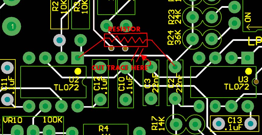
Upon exampaning the Quavearto circuit I think what would help this issue of being so bright when a buffer is plugged into the pedal is a resistor between pin 1 on U2 and the high pass and low pass RC filters. Attached is a picture of the PCB which indicated how to make this mod. You’ll have to use your xacto knife to cut a trace and then add a resistor between pin 1 of U2 and C2. A starting point for the resistor value should be between 1k and 10k. The larger the resistor the more immunity it should provide for the brightness effect. Please note that I haven’t had time to try this yet so this is only in theory. But if you do try it, please let me know how it works for you.
The capacitor mod I mentioned could have a starting value of 1nF….which corresponds to a LPF cutoff of around 16KHz. The value of C (in farads) is equal to 1/(2*pi*R*f), where R is the value of R2 (10K) and f is the low pass cutoff frequency you want. You can recalculate for whatever LPF cutoff you want.
-BrachParticipantCedric,
That will work. If you could send an email to info “at” zeppelindesignlabs.com and give us your name and email address then we’ll send you info on getting the pedal to us.
Just be aware that me looking at it may not change anything if I can’t get the pedal to reproduce the issues you are having.
Anyway, send us an email and we’ll be in touch.
-BrachParticipantThat’s good to hear that you got it working! Another person contacted us about the pedal not having a “tremolo” sound and it turned out that they did the same thing. It makes me wonder if our instructions could be improved.
Anyway, have fun with your new pedal!
-BrachParticipantCedric,
I’m sorry to hear that you are having this strange issue as well. I would really like to help you out, if you can get it to me and provide a way I can get it back to you. But I can’t promise anything because there is a good chance that other outside issues may be causing these problems. I also can’t afford to spend tons of time rebuilding the pedal completely if that is what it needs….depending on the build quality.
If you can agree to these things then please, send it in. Sorry to be so annoying, but in the past, we’ve gotten burned by my trying to be helpful in this way.
Let me know if you want to send it in, i’ll give you the details.
-BrachParticipantI’m glad to hear that it is now working.
This new problem of staying on sounds like another solder issue. I’m pretty sure just nicking the plastic with your iron wouldn’t damage the relay, unless you can see metal parts in there.
I’m assuming that the bypass LED stays on too….is this true?
…if so, you need to very closely check the solder joints around the switch (on both sides of the board). Use your continuity tester to make sure the square pad of the bypass switch is not connected to ground when the switch is not pressed (it should be connected to ground when it is pressed).
Let me know what you find.
Good luck.
-Brach -
AuthorPosts