

Forum Replies Created
-
AuthorPosts
-
 brachModerator
Ramin,
I’m sorry about this. I’m actually out of state right now on family vacation, but if you can send me an email with your serial number to info “at” zeppelindesignlabs.com I can get you the arduino source code. It may be a couple of days before i’m able to check my email again, but I’ll get it to you asap.
-BrachbrachModeratorI’m sorry about the misplaced insulation paper. All it is, is thick cardstock paper (that won’t get punctured easily), so you can just use that. It wouldn’t hurt to cover it with a layer of electrical tape for extra puncture protection.
There is nothing special about the wire. You can use whatever insulated wire you have that will fit into the pcb holes. Don’t use thick wire that is hard to bend or barely fits into the pcb holes. Whatever wire you are using is probably fine as long as it fits that criteria.
Good luck!
-BrachbrachModeratorIt seems like it’s all working correctly as you described. Is the pedal not sounding correct to you?
Remember the calibration values given in the manual are arbitrary values to just ensure the circuit is working more or less correctly, and by your measurements, it is. Keep the high trim pot set to whatever gives you the lowest value and then adjust the low trim pot until you like way it sounds. Make up for any low signal levels with the gain trim pot.
Also remember when you measure the resistance of the test points, you are measuring the LDR resistance in the optoccoupler while the LED light is shining on it, which the trim pot is controlling the brightness of (see the schematic). That is why the resistance is going up to megaohms/open when the light/power is off.
-BrachbrachModeratorThat sounds like a very interesting product. That would be a very practical piece of equipment to have around.
To answer your question, yes the Altura has a powered midi jack.
Good luck with the Widi Master!
-BrachbrachModeratorI’m so glad to hear you got it working again! Good job!
If you wanted to re-install C17 you might need to get creative with how you wire it. The original pads on the board are not able to be used so you you’ll need to run jumper wires from the cap leads to the output jack tip and pin 3 of Q3 (as per the schematic). But that’s only if the relay click starts bothering you. If not, just keep it as is.
-BrachbrachModeratorExcellent! Great work fixing that. Now we can work on the original problem.
Yes, the place to start is with the optocoupler circuit. Right now, the only thing that i’m sure of is that the LED in the optocoupler’s aren’t lighting up. That could be caused by several issues. Let’s start with the voltage to that circuit. As you see on the schematic, R7 and R8 should have 5V on one pin. Are you getting 5V both or either of them? If not, this diagram shows the 5V rail to both those resistors:
https://zeppelindesignlabs.com/wp-content/uploads/2023/06/5v-rail-jpg.webp
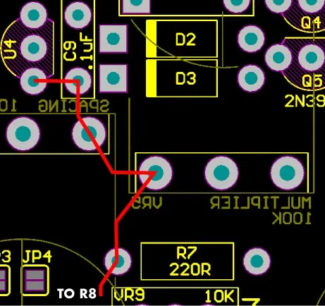
If 5V isn’t getting to both of them then the problem is probably a broken trace or something between VR5 (the multiplier pot) and R7…assuming VR5 and VR1 (spacing pot) are getting 5V. If R7 and R8 aren’t getting 5V then run a jumper as needed from any 5V source, but preferably from C9 seeing that it’s close to the source.
Let me know if that works or not.
-BrachbrachModeratorI’m glad you have confidence in your meter. Do you have as much confidence in your meter as in your ability to read it correctly (if it’s one of those analog meters)? I know for me those analog meters can be confusing.
I was referring to the relay continuity tests…when I was asking about power on or off, not voltage tests. Please let me know about this.
The voltage on R28 is of no consequence because C17 is removed.
The voltage on pin 5 of U2 is not off enough to keep signal from passing through that opamp.
If the optocoupler’s LEDs are not lighting up, then that would cause no signal to pass through the pedal when the bypass LED is on (when the effect is engaged). It would be unlikely that both optocoupler LEDs are not working, so are you sure this is happening? Either way, as I said earlier, you have more than one issue going on here because you are still not getting signal through the pedal when the bypass LED is off (the effect is bypassed). This is a much bigger issue than the previous one. The signal path is very simple in the bypass circuit….from the input jack tip, through the relay, to the output jack tip. If you are getting signal into the pedal and it really is not passing through to the output jack (when the effect is bypassed) then it can only be 1 (or 2) of 2 things: either there is a bad or broken connection somewhere (most likely a bad solder joint) or the relay isn’t working correctly. In conjunction with your meter testing this circuit, also please actually try it out with a real guitar signal (it’s important to try it both ways).
This problem (of the pedal not bypassing any signal) suddenly started when you re-flowed the solder joints and removed C17, correct? So it stands to reason that something you did in that process is causing this. Check all those connections that you touched up with the soldering iron. Make sure the input and output jacks are soldered correctly (re-flow them). Make sure the remaining pads (and traces) of C17 are not shorted to ground (see if the output jack tip is connected to ground…continuity test this). Is the relay really switching? You can test this with your continuity tester by following this image:
https://zeppelindesignlabs.com/wp-content/uploads/2023/06/relay-jpg.webp
The red lines represent the continuity you should have when the effect is engaged, and the blue lines represent the continuity you should have in bypass. Make sure you are testing the correct pins. This picture is taken from the top of the board, but it’s symmetrical so the bottom of the board is the same.
Please take the time to go through (and do) EACH of these things I’ve listed here in this post, until you find the problem. Let me know what you find.
-BrachbrachModeratorAre you making these tests while the pedal power is off or on?
In your re-flowing the solder joints something must have changed…most likely something was shorted. Make sure that the pins of C17 aren’t shorted. You may just want to try it out with a guitar to see if signal isn’t making it’s way through while the effect circuitry is bypassed.
It seems like there may be several different issues that are causing these problems (or possibly inconsistent/intermittent test results). In cases like this we need to eliminate each potential issue in hierarchical order. The issue at the top of the list is your meter. You probably should wait until you get a trustworthy meter that can give you good results before you continue. I’ve used a few old radio shack meters before and from my experience they aren’t very reliable.
-BrachbrachModeratorWow! You are quite a distance away from me right now. The internet has made the world such a small place.
Something might be wrong with your continuity testing. You said you were not getting continuity between the input and output jack tips when the bypass switch is off (which means signal will pass through your pedal when the LED is off)…but in your first post you implied that you were getting signal through the pedal when the bypass switch was pressed (when the LED is turned off), and then when the bypass LED is turned on, the signal drops in volume, unless I read into your post the completely wrong way.
Anyway, this makes me have a hard time trusting that your continuity tests are accurate. Could you please let me know if you are getting signal through your pedal when the bypass LED is off?
-BrachbrachModeratorThat’s correct about C17 being in the same circuit as Q3. So if there are no shorts across the pins of C17 then Q3 is not the main problem. It is still not behaving correctly because of your voltage measurements, but that’s not the thing causing no signal to pass through the board because C17 is removed.
You are right, it could be the relay. Go through steps 5-7 on the troubleshooting guide (assuming it passes all the steps up to that point). If that doesn’t help you may consider following the steps in appendix A to see if the LEDs in the optocouplers are working correctly.
-BrachbrachModeratorwaynemcl,
I’m glad you got it figured out. Capacitive touch systems can be pretty finicky sometimes. Usually altering the resistances is enough to get this system stable again.
-BrachbrachModeratorwaynemcl,
Sorry about the trouble…I just sent you an email.
-BrachbrachModeratorThat’s exactly what I would expect on R29. Good, there is no continuity across the pins of C18.
So once you pulled C17, did the pedal start working?
Are you testing for continuity with the power on or off?…because it should be off.
If it is true that you are getting continuity across the pins of C17 after it is removed then that is a problem. You must have a solder short across those pins. Please fix it or re-test it for continuity. They should not be connected.
If you are getting continuity between any 2 pins of the ISP header then there are solder shorts across them or something else in that circuit. See the schematic for more details. You must be doing at least one thing wrong because one of the ISP pins should be connected to ground. Please re-test these pins.
The main question is did the pedal start working when you pulled C17? If not, check for continuity across those cap pins…fix it if they are shorted. If it did start working after you pulled the cap, then the fet is probably bad or the ISP header has a short across 2 of it’s pins.
-BrachbrachModeratorPeter,
At least one problem is with the silencing circuit, with R28. If that pin isn’t high (around 5v) then the output will be silenced. Please make sure the isp header pins aren’t shorted. Also make sure C18 isn’t shorted. See if you are getting 5V on one of the pins of R29, as the schematic indicates. If there are no shorts across any of those pins (checked with a multimeter continuity tester) then temporarily remove C17 to see if the shorting circuit is broken (heat up both pins at the same time while gently lifting it off; then use a solder sucker to clean out the holes). It is possible that the FET could have been damaged.
Don’t worry about the voltage discrepancy on the U2 pin for now.
Unfortunately, we’ve packed up all these circuit boards into kits, so we don’t have any available to sell by themselves. The good news is that circuit boards are very difficult to damage past the point of repair. If traces are broken, you can always run jumper wires in their place. If pads are lifted, you can always run components point to point or connect them with wires. There’s almost always a way to fix circuit boards…the schematic makes it pretty easy to see where everything goes.
Let me know what you find.
-BrachbrachModeratorI’m almost positive that nothing got fried.
Are you saying that it unusually quiet when the effect circuitry is being bypassed and basically off when the effect is engaged until you crank up the volume?
This is a very common occurrence when there is a bad solder joint in the circuit somewhere. Often times, with bad solder joints, the signal can’t quite get through until the volume is cranked up and the signal has enough power to push through the high resistance of the bad joint. Once it pushes through, it often works for a while (even at lower volumes) but eventually cuts out again. I suggest that you re-flow all the solder joints in the analog part of the circuit, but you might as well do the whole board while you are at it. If there is a bad joint one place, there are likely to be others. When i say “re-flow” what I mean is heating up the joint enough to melt the solder so you can touch the solder wire to it. Not to add more solder, but to add more flux, which is incased in the solder wire. The flux is the stuff that boils and smokes when the solder is heated. It helps the solder flow better and most importantly it seals the joint so oxygen can’t penetrate it and cause it to oxidize. Oxidized joints (aka cold solder joints) become brittle and easily crack.
This is why the physical shape of the solder joint is important…when the joint is jagged or has irregular blobs on it, the flux can’t flow properly around the joint to seal it (mostly due to capillary action). Properly shaped solder joints allow solder to easily flow and settle on the surface of the joint, which protects it from oxidation.Good luck.
-Brach -
AuthorPosts
