- Your cart is empty
- Continue Shopping
Modding A Cheap Fuzz Pedal
Adding more control to a Fuzz Face clone

In the past few years I’ve developed a new hobby of trying out different Chinese made guitar pedals. I love discovering new, good-sounding pedals that are dirt cheap. Most of these types of pedals I purchase to try out are under $25, which is not much more than what I would have to spend if I were to build my own pedal…besides all the time I would have to spend on designing the PCB, populating the components, drilling the enclosure, and wiring up the electronics. I’ve discovered that modifying these cheap pedals is nearly as fun as building my own. One reason it is so fun is that modding pedals is much easier (in some ways) than building from scratch because I get to work on an existing circuit platform to try out new ideas. But the hardest part of the modding process is reverse engineering the circuit, so it helps when the schematic for the circuit is already available on the web somewhere.
One of the cheap Chinese pedals that I’ve discovered lately is the Cuvave Fuzz pedal (rebranded by a number a Chinese pedal manufacturers). The Cuvave has the classic rude and raucous velcro fuzz sound that many of us guitarist love. One of the most desirable characteristics of these types of pedals is the gating sound that they offer. This is caused by the circuit being under-biased in such a way that it will not “turn on” until the audio signal reaches a particular threshold, at which time the circuit sputters to life. The result is a farty, pulsey, sputtering sound that rock and roll guitarists love to use in the right context. On a side note, this is why some pedal power supplies have a voltage sag control; it helps to under-bias these types of pedals in order to get this type of sound.
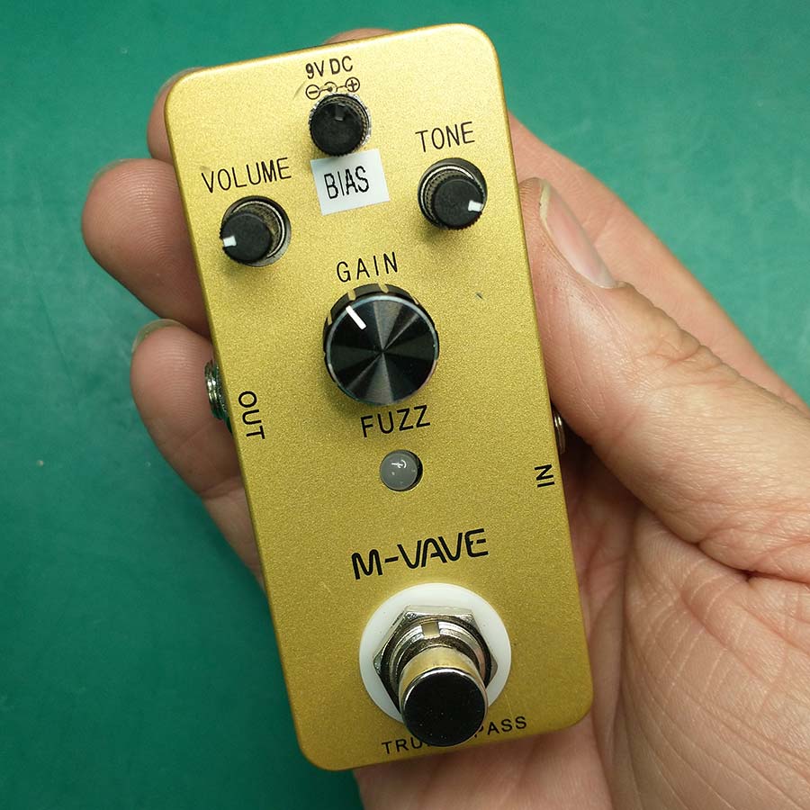
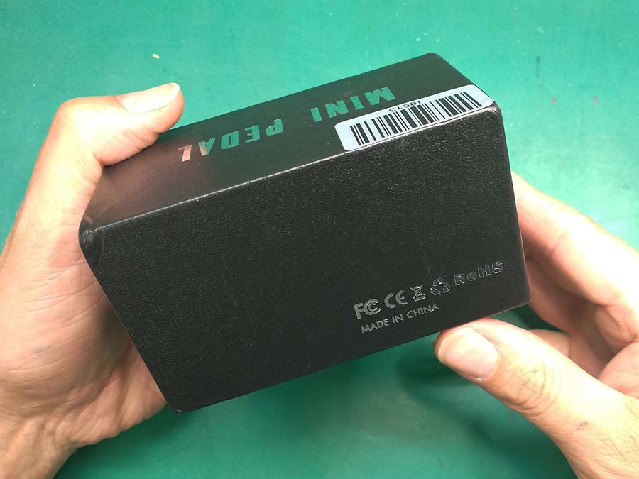
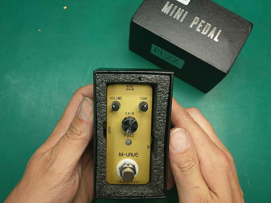
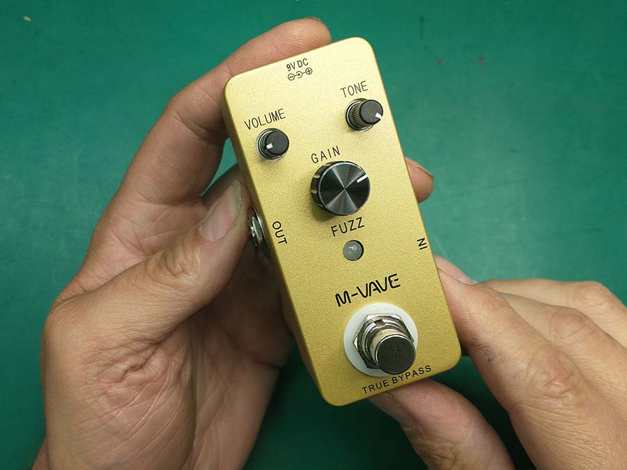
The particular version of the Cuvave Fuzz that I aquired from Aliexpress is called “M-Vave” made by some unknown Chinese manufacturer. It costs around $20 after shipping.

The Cuvave circuit is basically a fuzz face clone with an added tone control, which is the basis of many popular fuzz pedals today. I’m not sure when this pedal was released, but the original Cuvave had a really great gated velcro fuzz sound, demonstrated and made famous by this video from the 60 cycle hum Youtube channel. But with later versions of this same pedal, customers started complaining that it just didn’t have as much gain as the original, resulting in less gating and velcro sound…demonstrated in this video.
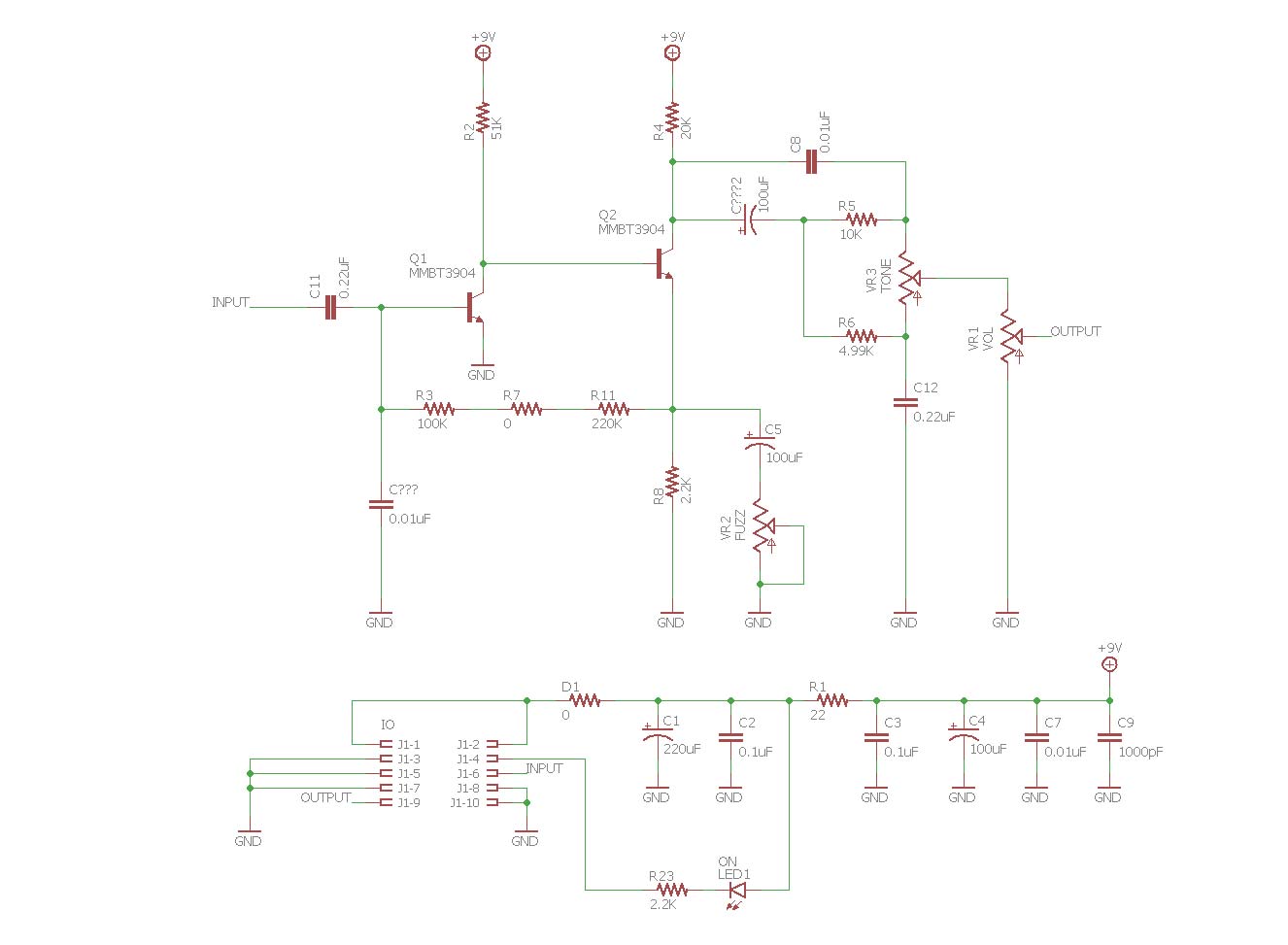
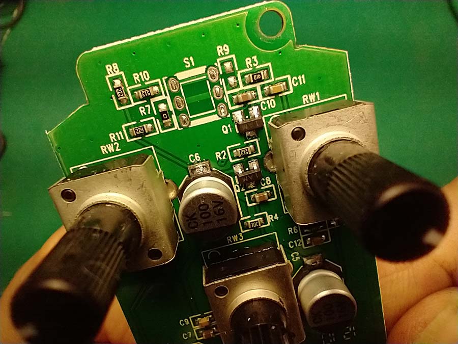
Some folks on the diystompboxes.com forum looked into the issue and discovered that the pedal manufacturer might have changed the value of a resistor (R7) in the feedback path between the two transistors. It was speculated that the original version of the Cuvave had a much higher value resistor as R7…somewhere in the neighborhood of 470K ohms. In the newer pedals, R7 was 0 ohms (as low as any resistor gets). But later in the forum thread someone posted circuit board photos of both the original and newer Cuvave. Surprisingly, they both had the exact same resistor values, not only in this feedback path, but throughout the board. So this tells me that the issue is actually with the active gain elements (the transistors) in the circuit. The original Cuvave must have had transistors with a higher gain (called “Hfe” in the datasheet) than the later versions of the same pedal. But from a modding standpoint, the good thing is that these differences can be compensated for by the feedback resistor network.
On a side note…As an American electronics manufacturer, it’s easy to think that the rampant counterfeit electronic component market is only a problem for manufacturers outside of China, but Chinese manufacturers are also really struggling with it. This case is a good example of this. It’s very likely that the manufacturer of this pedal got a batch of out-of-spec parts either in the original production run or in subsequent production runs…either way, the result is that now there are two different sounding pedals that are named the same thing. I suppose when you are only charging less than $25 for a pedal, you’ll take the components that you can get for the cheapest price, the actual component specs have to be an after-thought.
Anyway, let’s talk about how to correct this issue with the transistor gain. Without getting into too much feedback theory, I’ll try to explain in layman’s terms what the resistor network (R3, R7, R11) is doing. In general, feedback in a system is process of re-directing some of the output signal back to the input. By definition, this type of feedback always needs a loop in order to work and has to have a gain of over 1 (some energy has to be added to the loop somewhere). As an example, think of your guitar and your amplifier…when your amp is cranked up loud and you bring your guitar close to the speaker, you start to hear a high-pitched ringing which is known as “feedback”…the frequency of which happens to be the resonant frequency of that system, determined mostly by the length of your guitar strings. When this feedback happens your amp’s speaker moves enough air to cause the strings on your guitar to resonate, which causes the speaker to move more air, which causes the stings on your guitar to resonate…etc…it’s a loop. This type of feedback, which increases gain, is known as “positive feedback.” But a feedback loop can work the opposite way too. If the output signal happens to be 180 degrees out of phase with the input when a portion of the output is fed back into the input the gain is reduced. This type of feedback is known as “negative feedback.” Surprisingly enough, negative feedback is very useful in electronics circuits to help linearize distortion, extend bandwidth, and reduce the effects of component variation (due to manufacturer tolerance or the effects of temperature/humidity sensitivity). The key to using negative feedback in circuit design is to only use as much as you need and no more. There are 2 ways to change the gain in a system that contains a negative feedback loop: One way is to alter the impedance/resistance within the feedback path, and the other way is to change the gain (aka energy) added to the loop.
The Cuvave (fuzz face) circuit uses negative feedback by feeding some of the (out of phase) output from the second transistor (Q2) back into the input of the first transistor (Q1), via R3, R7, and R11 (see the schematic). Remember, negative feedback REDUCES gain, so the more negative feedback the input gets, the less gain the system provides. So if we wanted to increase the gain of this pedal, we could change the transistors to a type that offers a much higher Hfe, but that would be annoying to try to find transistors that match the correct footprint on the circuit board and adheres to all the other component parameters that this circuit requires. So the other (much easier) option to increase the circuit’s gain is to increase the resistance of the feedback network (R3, R7, and R11) so less signal is fed back to the input. And that’s just what the folks on the diystompboxes.com forum discovered. Many people reported that the newer pedals started sounding like the original after changing the value of R7 to a much higher resistance.

In modding my own Cuvave, I decided that I’d like to have more control over the pedal’s tone than what the 3 knobs offer. I decided to make the resistance of the feedback network variable. Essentially, I just removed R11 and wired a 500K potentiometer to its pads, while keeping R3 and R7 as they were (100K and 0 ohms respectively). So the least amount of feedback resistance will be 100K ohms and the most will be 600K ohms (500K pot+100K resistor).

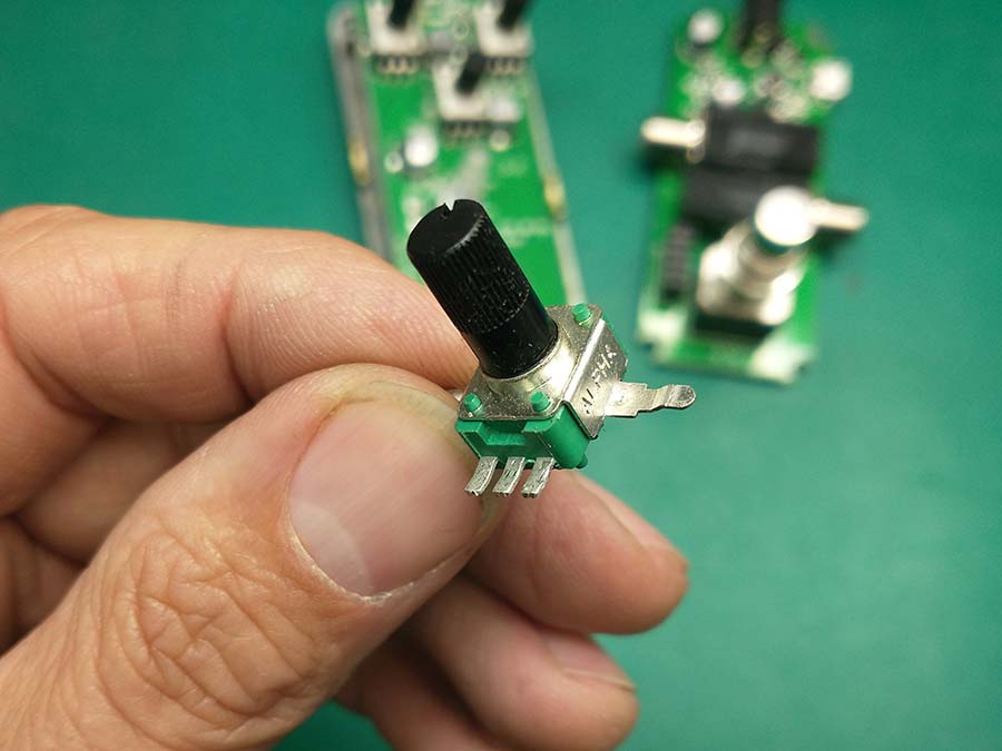
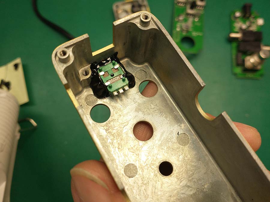
I used a 9mm potentiometer, just like the other pots on the circuit board. I modified the potentiometer so that it would fit in the limited space available for it by cutting all the legs short.
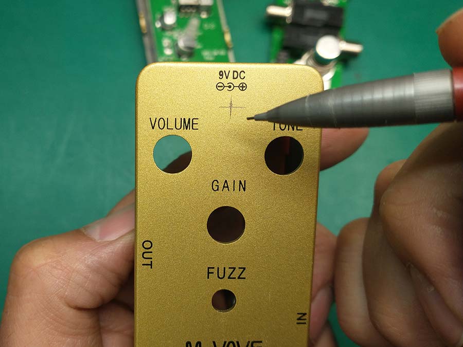
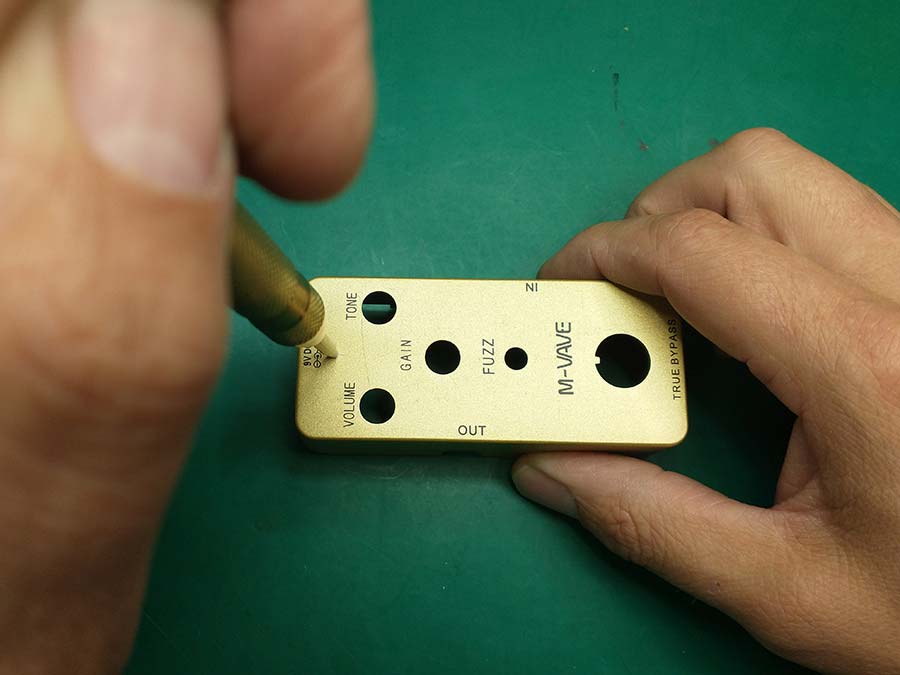
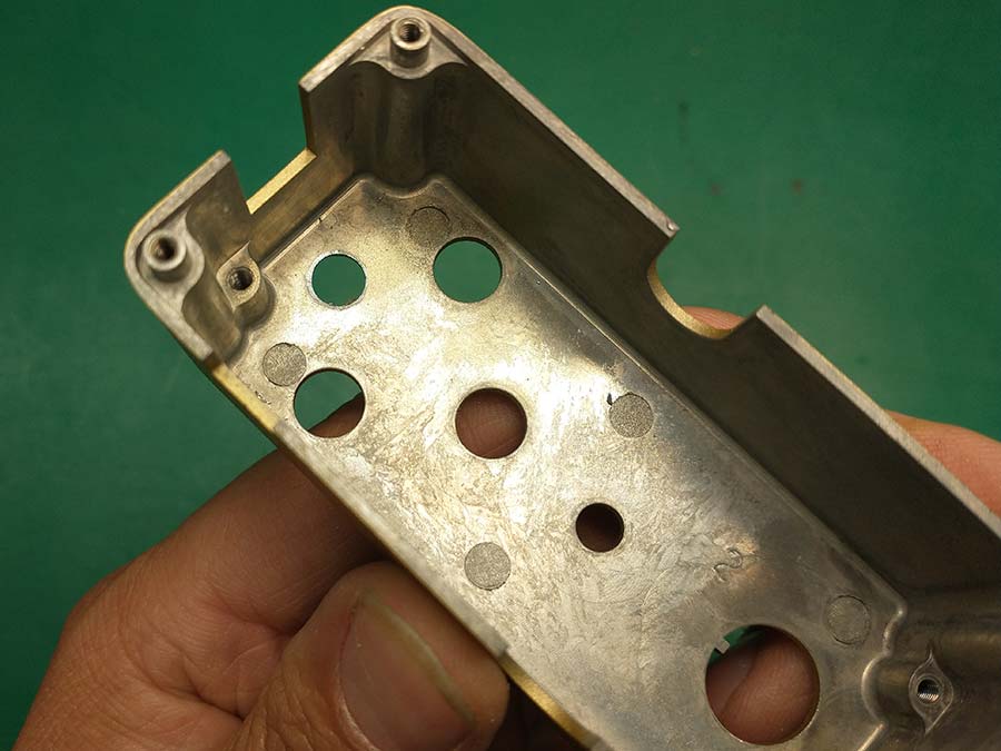
I then drilled a hole in the enclosure big enough for the pot shaft to fit through and hot glued the pot to the inside of the enclosure.


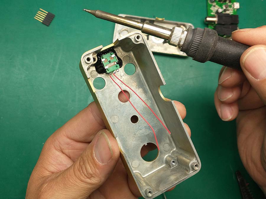
I then used 30awg wire wrap wire to solder some leads to the pot legs.
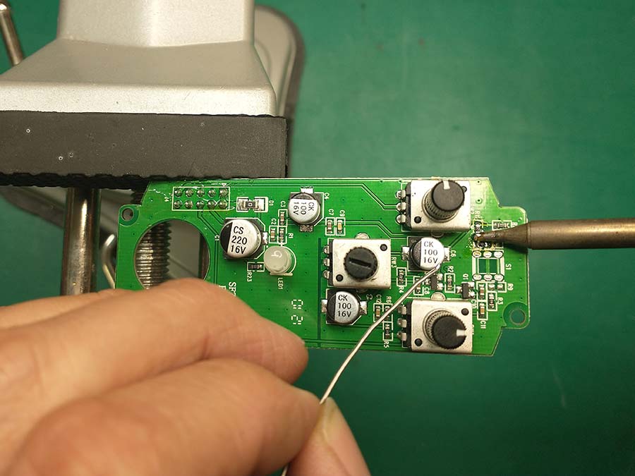
I removed the 220K ohm resistor in R11’s location. Then I cut the potentiometer wires to length and soldered the other end to the pads of R11. I made sure the wires were only as long as they needed to be so they didn’t bunch up between the circuit board and the enclosure.


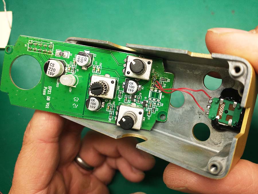
I put some hot glue on the wire’s solder joints to help ensure the wires don’t break when I assemble everything together.

Then I re-assembled and tested the pedal. The new control works very well to add more distortion, gating, and gain to the signal. At the fully clockwise position, the pedals has way more of a gated velcro fuzz sound than before. But I can also dial back the knob and get as much or even less gain than the pedal originally had. I ended up calling the new control “bias” and I labeled it with my label maker.

Overall, I really like the control this mod gives to the Cuvave. Even if I had an original Cuvave (with more gain/gating), I still would still do this mod because of the tonal versatility it offers. If I were to do this over again, I think I would probably replace the R3 (the 100K ohm resistor) with the potentiometer and keep R11 as it is (220K ohms). That would give me the option of having even more gain/gating if I wanted it. But for now, this will work for me very well.