- Your cart is empty
- Continue Shopping

Modding a Donner ISO 8 DP-3 Pedal Power Supply
Making this model of power supply more useful for a board full of 9V pedals

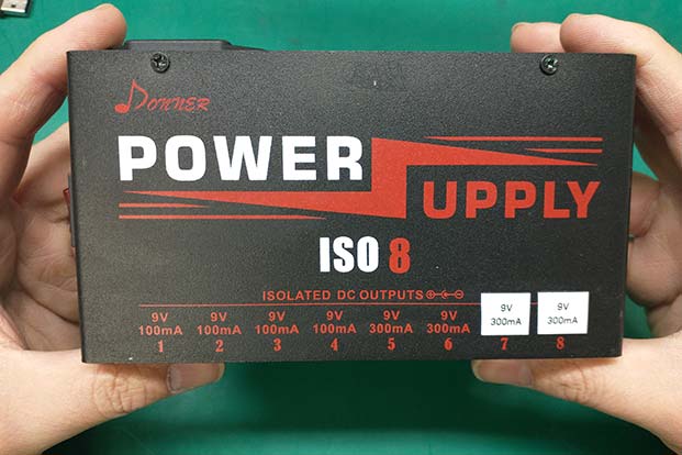
As a guitar player who builds a lot of pedal boards, I am very aware of the need for good power supplies. The best multiple output powers supplies for most pedal boards consist of fully isolated outputs. This means each power output does not share it’s positive or negative connection with any other output. Cheaper pedal power supplies often share the ground connection between all the outputs, which can allow current to flow in the ground path between pedals, causing noise in the signal chain. This is what we call a ground loop. The way most manufactures get around this problem is to use a power transformer with several isolated windings on it, each connected to its own power supply circuitry. This type of power supply configuration is relatively expensive because these multiple tap transformers are not cheap to make. So I was very excited to find out that Donner (a Chinese guitar pedal and accessories company) was producing these types of power supplies for about half as much as the “name brand” companies. These Donner power supply models seem to be a direct copy of a certain name brand company (that rhymes with “Loodoo Vabs”). The Donner DP-4 model has eight total outputs, six of them are 9V/100mA (with 2 of those outputs adjustable via a “sag” pot); the other 2 outputs are 300mA and switchable between either 9, 12, or 18 volts. The Donner DP-3 model is a simplified design, with four 9V/100mAoutputs, two 9V/300mA outputs, one 12V/300mA output, and one 18V/300mV output. I have a couple of these power supplies in both models, and I really like them. As far as I can tell, they behave just as well as the “name brand” power supply (which I also have). But personally, I don’t use many pedals that need 12V or 18V so these higher voltage outputs aren’t of much use to me; I would much rather have all 8 of the outputs be at 9 volts. So in this blog I’m going to focus on just the DP-3 model, and show you how I modded it to make all the outputs 9 volts.
I’ll give a little more detail of how these power supplies work so you can better understand what the mod is doing. As I said before, this type of power supply has a built in transformer with 8 separate secondary coils on it. Each of these coils is rated at either 10, 12, or 18 volts AC (depending on the output voltage), and can supply either 100mA or 300mA. Each coil has its own rectification and voltage regulator circuit, which produces the DC voltage that we need to run our pedals. The amount of DC voltage on the output of the circuit is determined by a single resistor in the voltage regulator circuit. The 12 and 18 volt outputs on this power supply have a different resistor in this circuit than the 9 volt outputs. So to change these two outputs to 9 volts, all we need to do change the particular resistor in their regulator circuits to the same resistor value that is in the 9 volt regulator circuits.

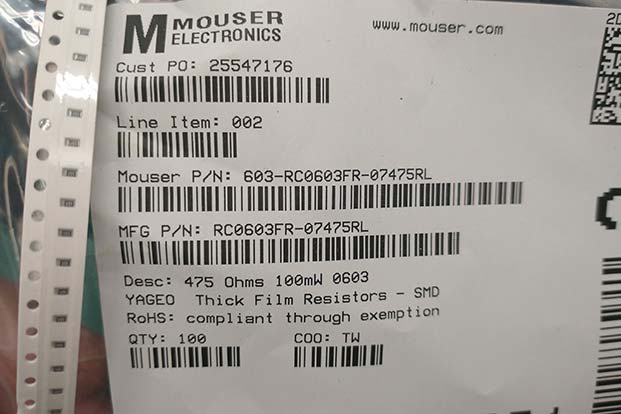
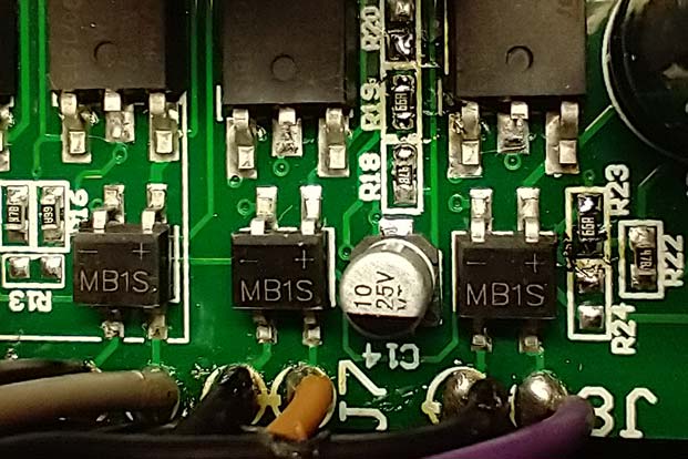
After opening up the power supply chassis and doing a quick examination of the circuit board I found out that the only difference between the 9 volt regulator circuits and the 12 and 18 volt regulator circuits is one 475 ohm resistor (labeled “66A”). The 12 volt circuit had a 330 ohm resistor (R19, labeled 331) and the 18 volt circuit had a 220 ohm resistor (R23, labeled 221) that need to be replaced.


These surface mounted components happen to be 0604 size which are more annoying to work with than the 0805 sized resistors that I keep in stock in my lab. Since I don’t stock this size or resistor, I had to order it from Mouser.
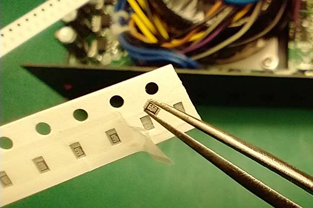
From this point, the process is pretty straightforward….it’s just replacing the resistors. Surface mounted resistors are pretty easy to solder. I use a technique called “floating” them off. It just means you heat up both solder joints on the resistor quickly by moving the iron tip back and forth from on the resistor’s solder pads until it heats up enough to come loose. These small resistors usually stick to the iron tip when they come off, so you don’t really need any tweezer to remove them. But tweezers are needed when soldering the new resistors to the board. After cleaning most of the old solder from the pads, the resistor needs to be held in place as one side of the resistor is soldered to one pad. Then the other side is soldered to the other pad. It’s pretty simple in concept, but from a practical perspective it can be somewhat annoying dealing with resistors this small, in which a magnifying glass or microscope should be used to ensure good solder joints (a magnifying glass isn’t needed when working with 0805 resistors…at least for my eyes, currently).
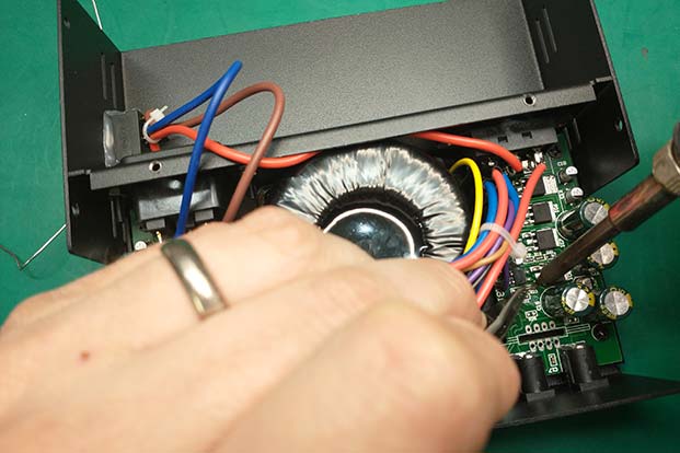
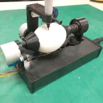
Another annoying thing about this particular job was the transformer wires were always getting in the way of either the tweezers, soldering iron, or my view of what I was doing. But I really can’t complain, it was about the simplest mod that can be done.
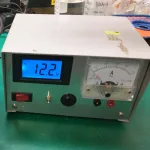
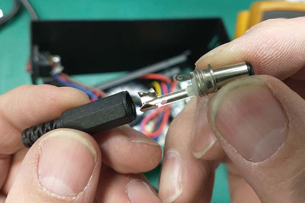
After I got everything soldered up, I tested both the 12v and 18v outputs to ensure they were now at 9V. I used a male barrel jack connector to give me an easily accessible test point. It all worked the way it was supposed to.

As a last step, I re-labeled the printing on the top of the chassis to indicate these two outputs are now at 9V.

I hope this inspires you and gives you sufficient information to mod your own power supply!