Forum Replies Created
-
AuthorPosts
-
 brachModerator
That’s too bad. I can get you spares for basically the price of shipping. Email us with your address and I’ll send you a paypal invoice.
-BrachbrachModeratorI’m sorry, I wasn’t meaning for you to have to remove the optocouplers. The LED’s polarity should be tested using your meter’s diode tester. With the red probe on the LED’s square pad and the black probe on the round pad, the meter should read around 1.8V (which is the forward voltage drop of the LED). If it reads around 1.5V then reverse the probes and check again. If when reversing the leads (red on round, black on square) it gives a reading of 1.8V, it means the LED is in backwards.
The LED’s turn-on current is rather specific for this application so please don’t use just any 5mm (not 3mm) green LEDs. I don’t remember the specs off the top of my head, so if you do need to replace the LEDs then let me know and I’ll try to find the specs you need to use…hopefully you don’t have to replace the LEDs.
If the LEDs in the optocouplers were in the correct orientation, I was going to have you make a small cut in the heat shrink so you can see what the LEDs are doing as the treadle is moving. You can always repair the cut with caulk or sticky tack or opaque hot glue or something. But this will give you a good idea if the problem is with the digital circuit or analog circuit.
-BrachbrachModeratorCole,
I’m sorry about your VPM-1 issues.
U2 is labeled on the voltage chart. It’s the IC in the middle of the board. Make sure the pins are -9v and +9v, as labeled.
You pedal’s symptoms are odd. It kind of sounds like the microcontroller may be screwy. You may want to do step D-3…it could fix the issue. The other thing to check would be to ensure the LEDs in the optocouplers are orientated correctly…the long pins should be in the square holes. Check that stuff and report back.
-BrachOctober 14, 2022 at 12:21 pm in reply to: VPM-1 expression upgrade – ability to switch between expression and volume? #40316brachModeratorI suppose all that’s really necessary to do what you want is to flip the expression dip switch (switch 4 on the main board dip switch). Repatching anything isn’t really necessary if you don’t need to use the tuning jack for your audio signal…you can just keep your expression cables plugged into the tuner/exp jack. I’ve heard of at least one customer wiring a “break-out” switch to the dip switch pads so they could more easily switch them without removing the module. That may be a good option for you. I don’t know where you’d mount the break-out switch, but electrically it should work.
…just an idea.
-BrachbrachModeratorI just wanted to update anybody who is looking on this thread….
We’ve recently developed a mod for the VPM-1 that allows it to fit into the larger Ernie Ball volume pedals, not just the Jr. line. See the VPM-1 Large Format Adapter page for more info…https://zeppelindesignlabs.com/product/vpm-1_large_format_adapter/
-BrachbrachModeratorOff the top of my head, I can’t remember the direction you’ll need to turn the trim pots. But it should be pretty obvious if it’s getting louder or softer once you turn it about 10 full turns in one direction. You’ll want to turn it in the direction that makes it louder.
-BrachbrachModeratorPat,
I’m sorry for the late response. I just got back in town from the holiday weekend.
You are on the right track with adjusting the tone trim pots in order to get the depth “deeper”. You’ll need to put the pedal in calibration mode to adjust the individual sides (high and low) separately in order to adjust their depth to the maximum setting. Keep the depth pot at max and set the phase switch to “in” while you do this. You may want to start by turning up the high trim pot all the way and then turn up the low trim pot to (tonally) match it….or vice versa.
Remember the suggested 5K trim pot value was only a starting point to ensure the pedal works. The final adjustment (and tonal balance between sides) is done with your ears…so there is no need to use your meter to re-measure the test points.
-BrachbrachModeratorOh! Good job finding that! Those resistors are quite different in value (14k ohms vs. 1 million ohms)! Yes, 14k as R1 in the input would have rolled off quite a bit of high frequencies.
I’m really glad to hear it’s working properly now.
Once again, good job finding those resistors, I probably wouldn’t have thought to look in that direction.
Enjoy your Quaverato!
Take care.
-BrachbrachModeratorI’m really glad to hear you enjoyed the Quaverato kit! It’s so fulfilling to get that sense of accomplishment when it works the first time you power it up. I hope it gives you years of great tone!
Thanks so much for the positive feedback!
Take care.
-BrachbrachModeratorThanks for the response. That tells me a lot.
So if adjusting the tone trim pots fixed the volume issue then that tells me we are on the right track. When the sound is muffled like that, it usually means that the high side isn’t working, or is just way lower than the low side. So first of all put the pedal in “calibration mode” to ensure both the high and low signal paths are working. If the high side isn’t working then follow the troubleshooting guide about what to do in that case. If both sides are working then you’ll need to adjust the balance of the tone until you like it and then use the gain trim pot to make up for any volume lost. Start by turning down the lows and adjusting the highs up most of the way. Then move up the lows until you like the way it mixes with the highs.
PS: Remember, that in order to turn up the highs and lows you’ll need to turn the tone trim pots in the opposite direction that you turn the gain trim pot to increase the gain.
-BrachbrachModeratorI’m sorry to hear that your pedal isn’t working correctly.
I’ll need to get some more information from you…
Did it ever work correctly? From your post in January it seems like it started working….is that correct? It’s important for me to know if it ever was working right in order for me to troubleshoot it quickly through the forum without seeing it.
If raising the gain trim pot all the way up didn’t solve the problem then replacing it with a higher value is not a good solution.
How confident are you in your soldering work? My first guess of why this is happening is that something isn’t making a good connection somewhere…especially if the pedal once worked. This type of issue is common when there isn’t enough solder on the joints or if the solder joints weren’t heated up enough to get the solder to flow properly into the joint. So that’s the first thing to check. If you have any questions about your solder joints you can take some (detailed, in-focus) photos of your board and let me look at them.
The next thing to do is to turn up the tone trim pots (both high and low). Turn them up the same number of turns each as to retain the relative levels of each. Turn them up nearly all the way (around 20 turns) to see if that makes a difference. Remember the suggested values in the assembly manual were only starting points.
-BrachbrachModeratorVery Cool! Thanks for sharing the photos!
I love the roller-controllers. That looks like a road-ready rig. Great job!
-BrachbrachModeratorIt wouldn’t do any harm to have something pressed against the display. But on the other hand, it wouldn’t do much good either (at least on the new model). The 7 segment display is fairly robust and doesn’t get damaged easily. On the older model, where it is just floating in the headers, a clear pieces of acrylic would probably help hold it in better.
That’s my thoughts.
-BrachbrachModeratorThe tact switch pins 3 and 4 are just connected to the ground bus, so you can just connect one lug of your arcade switches to your breakout box’s ground wire…don’t even run a wire to the switch’s pad.
Connect the other lug on your arcade switch to pin 2 (only pin 2) of the switch on the board.
When you are holding the board up, with the pots at the bottom, pin 2 is on the top right of S2 and S3. Pin 2 on S4 is the top left pin.
I hope that makes sense.
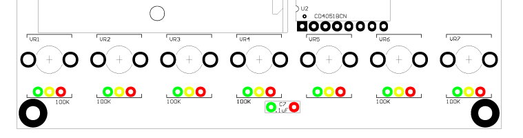
-BrachbrachModeratorThere is a schematic on the second to last page of the assembly manual…that was what I was referring to when I was telling you to look at the schematic. I’m sorry, I didn’t realize that my explanation wasn’t very useful. Hopefully this graphic will help…
The green pads are ground (aka negative)
The yellow pads are the wipers
The red pads are 5 volts (aka positive)
So you only need 9 wires total sent to the foot controller: one wire for each pot (connected to the 7 wipers), and one ground wire and one 5V wire. The ground pins on all the pots on your controller should all be hooked together…with the ground wire from the board attached to one of those pins. The same is true for the 5V pins…they should all be hooked together and the 5V wire from the board attached to one of those pins.
I hope that helps.
-Brach -
AuthorPosts