Forum Replies Created
-
AuthorPosts
-
brach
ModeratorPeter,
Try setting your Flashback delay to buffered mode, instead of true bypass. A buffered pedal driving the Quaverato tends to work better because of the input impedance and the internal filter circuits. Another thing you could try while the Quaverato is in the pedal chain is to adjust the HIGH and LOW trim pots to settings that sound more natural. But I think you’ll find that driving it with a buffered pedal will help.
Good luck.
-Brach brachModerator
JG,
I’m sorry to hear you are having trouble with your Quaverato.
First of all, are you getting a voltage between 0 and 5v on pins 23 and 24 as you turn the rate and depth pots? If so, the problem is probably that your microcontroller got damaged by static electricity in assembly.
We have seen these microcontrollers get damaged by static electricity in such a way that some of the functions stop working properly. But it is hard to say, in this case, if the static only damaged some of the flash memory or has caused more permanent damage. Re-flashing the device very well may solve the issue, but unless you already have access to a USBtiny then I would suggest on getting a new pre-flashed microcontroller. Use our contact page to email us with your serial number and mention this issue and we’ll get back to you about a microcontroller replacement. But we can’t guarantee that this will solve the issue because we had no quality control over the way this pedal was built…but from my experience this will probably solve the problem.
Once again, sorry for your troubles.
-BrachbrachModeratorNate,
The schematic is at the end of the assembly manual (did you put your Macchiato together without the manual?).
The noise of the audio amp can be dependent on the impedance of what it’s driving. It’s designed to drive low impedance loads, like speakers, not high impedance loads like a guitar amp or something, although it does fine in that capacity in most applications. So that might be causing some of the noise. From my experience, I’ve had to be mindful of the gain structure of the Macchiato and what it’s plugged into. Try keeping the volume very low on the Macchiato and boosting the input on what it’s plugged into…or vice versa if that doesn’t work. It all depends on how the impedance of the 2 devices match. But i’ve had good luck getting the noise floor low enough for recording by playing around with these levels.You asked about getting more of a line level rather than headphone level. There’s not much difference. Headphone level can just supply more current, but can usually get to around the same voltage level into higher impedances. But if you want, you can replace the the amp IC with a buffer (to reduce the noise caused by the amp IC). Disconnect pins 3 and 5 from the amp IC and hook in a unity gain buffer (either an opamp or emitter follower or something). You may want to disconnect R20 and R22 also if you don’t want those filters tainting the signal. You’ll want to remove the speaker too, so that the low impedance doesn’t strain the buffer.
-BrachbrachModeratorAre you talking about distortion or static (as in crackles you hear when your radio isn’t tuned to a particular station)?
Have you tried it with an external power supply to ensure that the problem isn’t with the battery (that may be low in charge)?
There is a noise floor on the Macchiato, but it should be very low compared to the audio signal you get; and you should get basically no sound when the volume is all the way down. If you are getting some sound with the volume down then that means the problem is with one of the components after the volume pot. Go through the schematic and just check to make sure all the components after the volume pot are correct and installed properly. The problem is most likely the LM386 audio amp or associated components.
-BrachbrachModeratorThank you for the pictures. I don’t know why you said your solder joints “aren’t pretty”. To me, for the most part, they look like the solder joints in the manual. Do you have a very high standard for what solder joints should look like?
Your board is very neat and clean, so that rules out many possibilities of what the problem could be.
Your pedal should only exhibit this behavior when the power is applied and you hold down one of the foot switches. What’s supposed to happen is when you apply power as you hold down the bypass switch for 3 seconds it should toggle the power-on state…either bypassed when powered on or engaged when powered on. Also, with the tap switch…when you hold the tap switch down for 3 seconds while you power it on, the green led should flash the software version. The weird thing is that your pedal is doing both these things while the power is already on. It appears that your pedal is constantly in a state of reset or something.
The first thing to do is re-seat your microcontroller to make sure it’s making good contact with the socket pins. Take it out of the socket and very firmly press it back in until the bottom of the IC is resting on top of the socket.
Also check the voltage of pin 1 of the microcontroller to make sure it is actually staying a 5V at all times.
You can also double check to make sure that the microcontroller pins and all of the pins on the ISP socket don’t have any tiny strands of solder shorting any of the pins together….re-flow them if in doubt.
You can also check to make sure the wiring from the foot switches are not shorting to ground accidentally. Use your multimeter 200 ohm setting (since you don’t have a continuity tester on your meter) to measure the resistance between microcontroller pin 3 and the round pad of the bypass switch port. Also measure across the microcontroller pin 4 and the round pad of the tap switch port. You should get a very, very low resistance…close to 0.
If all these things look good then your microcontroller might need to be re-flashed.
Let me know what you find.
Good luck.
-BrachbrachModeratorOf course…
info “at” zeppelindesignlabs.com
Thanks.brachModeratorI’m sorry, I can’t get those photos to load on snapfish….it just has this blue sun that keeps spinning and won’t load anything. I’ve given it all night to load, but no luck. Are you sure that’s the correct link?…or am I even allowed to see your photos on that site without your login info?
brachModeratorMichael,
I’m sorry to hear about your Quaverato troubles.
Thanks for trying to upload some photos, but for some reason they didn’t load. Could you please try to upload them again. You’ll have to find an online photo host and then insert the “IMG” link. It would be very helpful if I could see some detailed pictures of both sides of your board.
You say that your solder joints “aren’t pretty”…that’s a good indication to me that most likely you’re issues are solder joint related. Your solder joints should look very much like the pictures in the manual, otherwise it’s very easy to connect things that shouldn’t be connected or to not get good connections where there should be. This is where it is helpful for me to see some photos of your board.
On point #1 above, you mentioned that you have to hold the bypass switch down for a few seconds and then the led would flash and the relay would flip on…are you holding it down as you power the pedal on, or is this after it’s already powered on?
-BrachbrachModeratorGerman,
Thank you for that excellent video. It was very informative. If pictures are worth 1000 words, videos are worth at least 1000000 words.
So it looks like your depth knob is not functioning properly. Please double check your solder joints on the depth pot and on pin 23 of the micro controller…re-flow them even if they look good. Also double check for solder bridges on both sides of the board, especially on the pins on that pot. While you have the board out of the chassis, turn it on and see if you still have this problem. It may be that a component’s lead is poking through the paper and shorting out on the back of one of the pots while it is installed in the chassis. Look carefully and make sure that’s not happening. While it’s out of the chassis try to slightly lift the pots off the board to ensure this isn’t happening.
Let me know what you find.
Good luck,
-BrachbrachModeratorOh yea! You’re right about the ground lug ring…I forgot about that! I was thinking you were talking about one of the pins on the depth pot. But you can certainly use that as a ground reference.
That solder is probably ok, but I’m always a little skeptical of generic Chinese made solder…I’m sure some Chinese solder is great, but I know others are not. I depends what kind of flux they are using and what kind of tin/lead alloy they are actually using…and how many contaminates it has. Those things make a difference in how well the solder will hold and flow, and also in how easily the solder will keep from being oxidized. This is the stuff we use:
It’s more expensive, but we know what we are getting. Partial rolls are available on Amazon too (it comes in little tubes).
-BrachbrachModeratorThere is no hold labeled ground that is connected to the depth pot. There is a hole labeled “GND” on one corner of the board, is that what you are talking about?
You’ll know the relay is working because you’ll hear it click when you press the bypass switch. If it is not working then that may be your problem (or at least one problem). You’ll need to double check your solder joints (especially look for bridges) where the wires solder to the board from the switch and on the switch itself. Also check the solder joints around the relay.
-BrachbrachModeratorThe voltages seem correct.
Set the harmonic mix and spacing knobs straight up, at the 12:00 position Set the multiplier at the 1:1 position. Set the wave shape to the square wave position. Try it again in this setting.
You refer to the “rate” of the led in your previous post…the word “rate” indicates speed. When you increase the depth knob, are you sure the led is blinking faster and faster, or is the blinking just getting more pronounced? Are you sure the depth knob is altering the rate of the blinking, instead of just the depth? Does the rate knob do anything?
After the depth knob has increased to the point of not being able to decrease (i’m assuming this means that the this knob won’t do anything anymore), what is the voltage at pin 23? I’m curious if it’s stuck at around 5V.
-BrachbrachModeratorThat looks much better. Good job. It will be much easier to track down problems now because we can probably trust that there are no (or very few) issues with assembly…and they will be easier to fix when they do come up.
Is the tremolo audio functioning yet? I just want to double check that the bypass switch is working properly before we do anything destructive like cut the LED trace. It does/did switch the relay, didn’t it? Also, when you measure the voltages, what point are you using for ground?…a good ground point is pin 1 of the input or output jack, which is the shield tab…it is the one closest to the edge of the board. It might also be good to double check your voltages before you cut the trace.
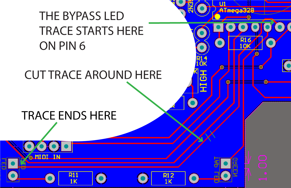
To proceed with cutting the trace (which isn’t that big of deal because you can always re-run your jumper to the LED from pin 6)…You can see in the picture were the trace from pin 6 comes from and where it goes. Use your xacto knife and cut a small section out of this trace…cut two lines across the trace 1-3mm apart and then peel up the cut trace in between the lines. Make sure you don’t accidentally cut the wrong trace.
Good luck!
-BrachbrachModeratorI’m sorry to hear that. What is the minimum and maximum DC voltage are you getting on pin 23 of the microcontroller as you turn that pot from far left to far right?
-BrachbrachModeratorOk, Good! It may be confusing, but at least it’s working correctly!
It would be more accurate to call it an “effect engaged” LED, rather than a “bypass” LED. Sorry for the confusion.
I’m glad to hear you like your pedal!
Take care.
-Brach -
AuthorPosts