Forum Replies Created
-
AuthorPosts
-
 brachModerator
What do you mean the relay does not switch off?…Is is stuck in one position or the other? What did you mean when you said you get a “full bypass tone and the effect stays on”? Does the signal run through the effect circuitry or is it bypassed through the pedal? I’m confused.
So for good measure let’s double check to make sure the relay is working…
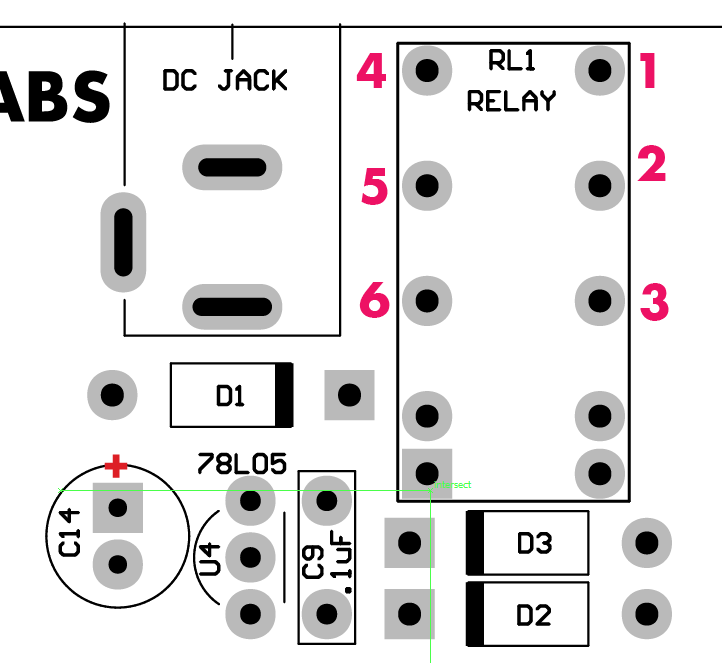
When the effect is on, as in when the red led by the bypass footswtich is on and you expect to hear the tremolo sound through the pedal, pins 1 and 3 of the relay should be connected and pins 4 and should be connected. Test this with your continuity tester.
When the effect is off and the signal is just bypassed through your pedal pins 3 and 2 should be connected and pins 6 and 5 should be connected. Please test these and let me know what you find.
If the relay isn’t working properly….
Try to re-seat your microcontroller in it’s socket. We need to make sure the pins that control the relay are making good connection. Be careful when you pull it out not to bend any leads.If the relay appears to be working properly then…
With the pcb out of the chassis, make sure each of the pots are bent slightly upward away from the board to ensure none of other component’s leads are touching the back of the pots.
With the depth knob set fully counter clockwise, what happens when you touch TP3 and/or TP1? Do you hear any noise? TP3 and 1 are directly before the LDRs.
Please be specific about which trim pot were you touching…VR8, 9, or 10?Let me know what you find.
-BrachbrachModeratorThat’s great that it’s working now!
Are you saying that TP3 has 12v on it? If so, it appears the LED has been damaged…probably by the spark. It needs to be replaced. You might also want to check TP2. Also check to see if there is any AC voltage on TP2. It’s good to make sure other components weren’t damaged as well.
Here’s a method that makes it easier to replace the LED with out removing the board… Clip the old LED off at the board and mount the new LED in the chassis socket and run jumper wires down to the pads on the board. To do this, cut the new LED’s leads fairly short and bend little hooks in them. Bend hooks in the jumper wires too. Hook the two hooks together (the LED lead hook and the wire hook) and bend them together with your pliers and then solder over the connection. You can use some hot glue or something to affix the LED to the chassis if it needs it.
Let me know if you have any questions.
Good luck.
-BrachbrachModeratorIf you can’t figure out where the current in the spark went to then double and triple check under the board and all around for any stray wires or tiny solder balls or anything that could cause something like that. That’s probably not something you want happening very often. As I understand it, the amp was on for a while before the fuse blew. Is this correct?
It sounds like your problem is the tube socket pins are too loose. If it was making contact you should be getting at least some voltages on the cathodes of those tube sections (TP5 and 7).
Keep me posted.
Good luck!
-Brach
PS make sure you clean the black burnt area on the board and IEC jack…it’s conductive and cause arcing in the future. Rubbing alcohol on a q-tip works pretty well for this.brachModeratorMy response:
Thanks for the photos. It’s always helpful to get a visual of what we’re talking about.
R1 and R7 are basically in parallel with each other so they should measure around 750 ohms each. And that’s fine if R4 is a few ohms off, it’s still within a it’s 5% tolerance.
You said it sparked at the ground terminal, but can you tell where it sparked to? There was/is some short of short against the ground terminal there….was a strand of wire touching it somehow? It’s important to know why that happened so you can ensure it won’t happen again. Please replace the fuse with a 1 amp / 250V fast blow fuse….nothing bigger!
The voltages you shared from your test points indicate that the tube isn’t installed…is it? If it is, then please tighten
all the tube sockets to ensure all the pins are making good contact.
Keep me posted on your progress.
-BrachbrachModeratorHearing static is a good thing. It means that the output circuitry is working. Actually the pedal was working at one time so you should be able to get it working again…this is why i think something is shorted or opened (as in a solder joint that isn’t making good connection.)
Let’s start at the beginning of the signal path…Can you hear any noise when you touch the relay lead closest to the edge of the board, on the side of the relay closest to the power led?…this is attached to the input of the effect circuit (make sure the volume pot turned up when you do this). You may even want to touch your guitar cable to this relay lead so you can inject some sort of signal into it (you’ll have to find another cable to plug into the input jack so the pedal will turn on).
You can go through the circuit this way, following the signal path in the schematic, touching various leads in the circuit that are next in the signal path. One bottleneck to look for is the LDRs. Are you hearing noise when you touch a point before the LDRs in the circuit…or just after?
Let me know what you find.
-BrachbrachModeratorWhen it is turned on and you have signal going into the effect, try to gently bend the pots around to see if you can do anything to get signal to come through the circuit. Give special attention to the volume pot…that’s the one pot that has direct control over the output signal. You can also try to poke and press on various components on the board to see if that makes any difference. The goal here it to figure out which component is shorting the signal or keeping it from passing through.
brachModeratorThat’s good. Is it still not working when it is out of the chassis?
brachModeratorIt seems like the relay is working now. This really sounds like the signal path is getting shorted to ground somewhere. I would keep it out of the chassis until you get it all working correctly. So if it’s in the chassis now, take it out and see if that makes a difference. Have you trimmed the sharp leads under the pots? Has the paper under the pots been punctured by the sharp leads?
Let me know.
-BrachbrachModeratorYes, that’s a start! That’s encouraging. It seems like something is shorting…like the back of a pot against a lead poking through the paper. Are you sure no leads are poking through the insulation paper? Make sure you trim all of the leads that are under the pots to ensure they can’t poke through….especially on the relay and microcontroller.
Use some different insulation paper if you need to. I think you are close to getting this to work.
The dark tone is probably from the HIGH side signal path not working due to the jumper issue…we can fix that once it is working reliably.
Keep me posted.
Good luck.
-BrachbrachModeratorExcellent photos. Thank you.
Now it sounds like your relay may be working properly after the microcontroller leads are thoroughly in the socket. Do you hear the relay click when the bypass switch is pressed?
Make sure that pins 15 and 16 are seated properly too because those are the pins that control the optocoupler LEDs.
It doesn’t matter how the socked is orientated as long as the IC in facing the correct way.
If the issue was with the jp2, which is the high frequency signal path, you would still hear the low signal path going through jp1, so i’m not sure that is the issue.
I noticed you have a lot of solder on most of the joints…double check all the solder joints, especially around U2 to make sure there are no shorts. I know you probably are doing this already, but make sure you use the insulation paper under the pots to ensure that nothing is shorted to the back of pots.
Let me know what you find.
-BrachbrachModeratorI’m glad you enjoyed you Quaverato build, but that’s too bad about it not working yet.
Are you saying that the signal is bypassed through the pedal no matter if the red bypass led is on or off?…as in you can hear the guitar signal on the output jack at all times? If that’s the case it sounds like the signal isn’t even going through the effect circuit…like the relay may not be switching properly. The jumpers would only matter if the signal was going through the effect circuitry. Don’t worry about jp2 for now, we can always bypass that with a jumper.
If you could send me some (detailed, in focus) photos of both sides of the board to info “at” zeppelindesignlabs.com (if you can’t find a way to post them on the forum), I might be able to see something. Pay close attention to the solder joints of the realay and the microcontroller. You may also want to re-seat the microcontroller in it’s socket to makes sure there’s no problems there.
Good luck.
-BrachbrachModeratorYes, the ZDL Updater software is pc only, at this point. Sorry.
Glen (our manager) should respond to you via email with info on getting a new microcontroller.
Once again, I’m really sorry for your frustration. We’ll get your Quaverato working soon.
-BrachbrachModeratorI’ve got to say, I’ve never experienced anything like this with this pedal. I’m sorry for the frustration and I commend you for your persistence. At this point we’ve pretty much ruled out everything that I can think of outside of the microcontroller. The Quaverato is a pretty simple pedal from an electrical perspective so there’s not much that can go wrong…Now that we’ve ruled out basically everything else I have confidence that a re-flashed/new micro will get it back to working. So maybe your original hunch was correct, that the micro was damaged somehow. It may have been damaged through static electricity in assembly…we test all these chips before we send them out so it was working at some point.
If you have access to a USB tiny you can re-flash it using our ZDL Updater software available on our website to see if that helps, or you can sent the chip into us and we can either re-flash it or replace it depending on what it needs.
Once again, I’m sorry for the frustration.
-BrachbrachModeratorAndrew,
I’m so sorry…I don’t know how i missed that you posted those photos. That gives me a good visual of your board. I’m curious if the board behaves in the same weird way when it’s out of the chassis, and the pots are pulled up a bit (away from the board) as in the photos. I want to see if something might be making a short to the board, like the pots or the chassis. It seems like some of the leads under the pots are long enough to potentially poke through the paper. Let me know about that.
It’s not easy to test the crystal with out an oscilloscope, but if the green led is blinking consistently then it should be working alright.
-BrachbrachModeratorIan Erik,
I’m sorry to hear about your Macchiato troubles. The guys at Koma should be able to help you. The first step is to re-flash it with the latest software. I’m guessing that will probably fix the issue, but if it doesn’t, let me know. Koma should have a USBtiny (if you don’t already have one) and you can use ZDL Updater Windows software available on our website (https://zeppelindesignlabs.com/product/zdl-updater/).
Good luck.
-Brach -
AuthorPosts