- Your cart is empty
- Continue Shopping
Forum Replies Created
-
AuthorPosts
-
brach
ParticipantI’m sorry, I don’t think it got to us…could you please try to send it again: info”at”zeppelindesignlabs.com (change the “at” to the @ symbol).
Thanks.
-BrachParticipantSorry for the bad news. Static electricity is very sneaky. Over the years I’ve damaged several microcontrollers by what I can only assume is static electricity. These IC’s can only handle at most 13 volts on a pin, but a static discharge isn’t even detectable by our senses until it is over 1000 volts…so they are really easy to damage without knowing it. And most of the time it doesn’t completely kill the chip, it only damages part of its functionality.
Unfortunately, these flashed uCs are only available from us directly, not any of our distributors.
But yes, please contact me via email and we’ll discuss this.
-BrachParticipantSo this conclusively tells us that the uC is the culprit. There’s no need to swap the transistors and please do not use sockets on them. Sockets have a tendency to become unstable over time, causing more problems down the road.
Unfortunately, this isn’t a warranty issue because the uC was most likely damaged in this way from static electricity in assembly. We do a pre-flight test on all these microcontrollers before they are shipped, so I can say it was working when we shipped it. We do sell replacement microcontrollers, if you don’t have a way to flash one. But if you are able to borrow a PC and get a usbtiny programmer (available many places online), the flashing procedure is very easy to do. We give step-by-step instructions in the updater app (press the “?” in the app window).
But all this being said, please contact me at info “at” zeppelindesignlabs.com and we can work with you to figure this out.
-BrachParticipantIf the voltages on the opamp are all correct (as per the voltage chart on the troubleshooting guide) then that part of the circuit is probably working fine. The only thing I can think of is either one of the resistors is not the correct value, or perhaps a solder joint is not making a good connection. If you can’t figure it out, you could take some (detailed, in focus) photos of both sides of your circuit board (clearly showing all the solder joints and components…you’ll have to bend up the pots on the solder side of the board to show under them) and I could see if there’s anything that I could notice that could be causing the is problem.
Good luck.
-BrachParticipantThat is very good information. This seems to point to the microcontroller (uC) because the signal getting from the uC to the high side transistor never gets down to 0 volts when the depths is up (unlike the low side). For some reason the pwm seems to never turn all the way off.
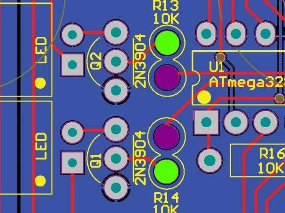
The real test is to find out how it behaves when the uC’s signals are switched between the high and low sides. You can try this by lifting one leg of R14 and R13.
https://zeppelindesignlabs.com/wp-content/uploads/2023/10/zeppelin_design_labs_quaverato_pcb-jpg.webp
In the pcb graphic, unsolder the green dots. Just leave the end of the resistors floating in the air while the other legs are still attached to the board on the purple dot. Find some very thin wire (I use “wire wrap” wire for these types of things) and run a jumper from the floating lead of R13 to the green pad of R14…and run another jumper from the floating lead of R14 to the green pad of R13.
Now turn on the power and test the optocoupler LEDs. If the problem is with the uC then the low led will start behaving like the high led used to, and the high led will start behaving like it’s supposed to.
If the problem is with the transistor (Q1) then the high led will misbehave the way it always has, and the low led will continue behaving correctly.
Let me know what you find out.
-Brach
ps I should have had you measure the resistance of R13 and R14 first to ensure they are really 10k or at least the same resistance value. So do that before you unsolder anything. If they measure different then unsolder one lead and re-measure them.ParticipantThank you for the videos, although I wasn’t able to see the second video…it seems to be a dead link.
But from the first video, I can see the problem seems to be with the LED, not the LDR (thank you for testing those resistances).
This is a really weird problem that I’ve never seen before. The issue has to be with either the LED or the driving circuit or with the microcontroller.
So to start on the top of the list, could you please measure the high side optocoupler LED with your diode tester on your multimeter (with the power off)? Just compare it with the low side LED to see if it’s the same. I expect it is.
If it passes that test, lets try to test Q1 (with the power on). Could you please turn the depth knob all the voltage on all the pins of Q1 and compare them with the voltages on the same pins of Q2? Then turn the depth knob all the way up (clockwise) and do the same thing. Keep the LFO rate relatively slow during this test so you can see the voltage changing. The voltage should be changing in relation to the LFO rate, so compare how the changing voltage on the pins of Q1 compare to the changing voltage on the same pins of Q2. Use the DC voltage setting on your meter to measure these. If both the transistors seem to be behaving the same then the problem might be with your microcontroller. But first please ensure that R14 is soldered correctly and is really 10K ohms in value. Then make sure pin 15 of the microcontroller is soldered well and it is seated well in the socket. If all that is good then you may need to re-flash the microcontroller. You’ll have to get a USBTiny programmer for that. We have the software on our website that you can download for free. After you do all these tests, let me know what you find.
-Brach
PS it doesn’t hurt to resolder all the pins on the components that I mentioned here…sometimes bad solder joints can look good.ParticipantThank you for the videos and audio. All this is reiterating the fact that the high side is not tremoloing the audio, and the low side is. If the high side was working correctly then your Quaverato would sound just like the one in the videos.
There is almost certainly not a problem with the pots, but you can test this by measuring the voltage on the center pin to see if it’s getting from 0 to 5 volts. The transistor is not bad because you are telling me the high LED is pulsing. If the transistor was bad then it wouldn’t work. We’ve already established that the LDR is working, at least somewhat. You can do some more tests to ensure that the resistance of the LDR gets up to at least 1M ohms or so when it is in complete darkness. Right now, it seems like the only potential cause for this is that the high optocoupler is not sealed well and is letting some light in, causing the resistance to remain low across the LDR, so it never gets to compete darkness (up to 1M ohms across it). But i’ve already asked you to seal the optocoupler well and i’m assuming you’ve already done this.
You can test the optocoupler (with the power off) by measuring the resistance across it’s pins in the darkness. You can test if it’s sealed well by shining a flashlight on it to see if the resistance changes. The resistance should get much higher than 1k7 ohms in the complete darkness. Test both LDRs this way to ensure they are both behaving the same.
-BrachParticipantFrom what you are describing, it seems like it’s working as it should. The mix knob is behaving correctly…when it’s turned to one side or the other it causes only one side to pulse while the other lets the signal through without pulsing. When it’s in the middle position (12:00) both sides should pulse the same amount.
This is making me wonder if you had the mix knob turned to one side when you recorded the sound sample. Can you test that again with the mix knob in the middle?
If you are looking for the pulsing sound, the phase switch needs to be set in the “in” position. Once you get the pedal working correctly, you’ll probably need to adjust the tone trim pots (high and low) to dial in the proper amount of both signals.
-BrachParticipantYes, the LDRs are very sensitive to even the tiniest amount of light.
So by that test we now know that the high LDR is not shorted and it is working, at least on some level. Just to clarify, when you cut the high optocoupler open, did you see that the LED was pulsing at any time (or at any knob setting), or was it just staying on all the time? Because the pedal is behaving like it’s just staying on and never flashing, at least according to the symptoms that I’m aware of. If this is the case then there could be a problem with the mix pot. Please ensure that the center pin of this pot is scrolling from close to 0 volts to close to 5 volts as the knob is turned from one end to the other. Otherwise, there could a problem with Q1…ensure it’s in the correct orientation and soldered correctly, without any shorts.
-BrachParticipantIf you haven’t measured the resistance (with the power off) across the test points (1 and 2), please do that…just to ensure there is no short or near-short on those pins. There may be a short on a part of the board that isn’t visible.
To find out if the LDR is defective you can always measure the resistance across TP1 and TP2 (with the power off), while you shine a flashlight in the hole you made earlier in the heat shrink. I’ve never seen an LDR short out or go bad, so it’s probably not that.
-BrachParticipantThat’s really good information to have…the high side audio is not pulsing (thanks for the audio clip, that was very helpful). The other piece of good information to know is that the high optocoupler LED is working. So there must be a problem around the LDR, like it’s possibly shorted. So from looking at the schematic, make sure TP1 and TP2 (or JP1 and JP2) aren’t connected/shorted. You can use your meter’s continuity tester to check this (with the pedal’s power off).
Let me know what you find.
-BrachParticipantI’m glad to hear you are liking the Quaverato, but I am sorry about this issue.
It sounds like you may have some leaky optocouplers. It seems like light is somehow making its way into the heat shrink, causing the signal not to shut off all the way. Please make sure you seal the ends very well with some opaque substance (even poster putty/sticky tack will work). Also, make sure you optically seal the holes you made in the heat shrink.
You can use calibration mode to tell what side (high or low) is leaky. Also, it’s best to use the square wave setting with the depth all the way to 100% (fully clockwise) and the LFO rate set relatively slow, so you can easily hear if the sound is not shutting all the way off on each cycle.
Good luck!
-BrachParticipantRamin,
I’m sorry about this. I’m actually out of state right now on family vacation, but if you can send me an email with your serial number to info “at” zeppelindesignlabs.com I can get you the arduino source code. It may be a couple of days before i’m able to check my email again, but I’ll get it to you asap.
-BrachParticipantI’m sorry about the misplaced insulation paper. All it is, is thick cardstock paper (that won’t get punctured easily), so you can just use that. It wouldn’t hurt to cover it with a layer of electrical tape for extra puncture protection.
There is nothing special about the wire. You can use whatever insulated wire you have that will fit into the pcb holes. Don’t use thick wire that is hard to bend or barely fits into the pcb holes. Whatever wire you are using is probably fine as long as it fits that criteria.
Good luck!
-BrachParticipantIt seems like it’s all working correctly as you described. Is the pedal not sounding correct to you?
Remember the calibration values given in the manual are arbitrary values to just ensure the circuit is working more or less correctly, and by your measurements, it is. Keep the high trim pot set to whatever gives you the lowest value and then adjust the low trim pot until you like way it sounds. Make up for any low signal levels with the gain trim pot.
Also remember when you measure the resistance of the test points, you are measuring the LDR resistance in the optoccoupler while the LED light is shining on it, which the trim pot is controlling the brightness of (see the schematic). That is why the resistance is going up to megaohms/open when the light/power is off.
-Brach -
AuthorPosts