

Forum Replies Created
-
AuthorPosts
-
 brachModerator
I’m so glad you are enjoying your Percolator!
Those mods sound nice. But I hope you ran a load line on the circuit to see if your transformer is within range to work for it. I don’t know anything about the Defender 5, but I hope that mod isn’t damaging your tube. Another customer tried to change the output transformer on this amp and ended up killing the tube and a resistor or 2. So I’m nervous about customers modding the OPT now, but you sound like you know what you are doing.
I made the frequency response of this amp a little wider than most amps, to make it sound “fatter” and “bigger” than it really is. After all these years, I can’t remember what frequency cut-offs I used. Most amps I design, I limit the bandwidth to allow it to fit in the mix within the context of a band, so it will cut through the mix better and be heard easier…more mid-range. I didn’t figure the Percolator would be played in any kind of ensemble, but rather in someone’s bedroom by themself where it’s nice to have a wide bandwidth, or in the studio where you can EQ it to fit into your recording.
-BrachbrachModeratorGood! I’m glad you figured the problem out.
It’s good to hear you are enjoying it! Hopefully building it and tweaking it was a lot of fun in itself.
Take care.
-BrachbrachModeratorI’ve never heard of anyone having those issues before. Did you say that the red power LED is blinking? It’s supposed to just stay on. Are you sure you are not using an AC power supply, or some type of power supply other than what’s specified? It should be 9V DC at least 100mA, center negative. Try a different power supply to just make sure it’s not the problem.
If the power supply is correct then make sure there are no shorted solder joints in the power supply section (see the schematic for details).
-BrachbrachModeratorCharles,
Thanks for your interest in the Percolator. I hope you enjoy building it.
The NFB loop is connected from the output to the cathode of a previous gain stage via a resistor (you’ll see the schematic when the kit arrives). You are correct, a good way to mod the circuit is to manipulate the NFB loop with either a feedback level control, some tone shaping (via an RC network), or a switch to disconnect it for extra gain in the midrange.
I’ve done this sort of thing with several different amps in the past, but it’s been so many years now since I designed the Percolator that I can’t remember the specifics of my experiments with it’s NFBL. Feel free to experiment with it yourself!
Have fun and take care.
-BrachbrachModeratorMrfurious,
I’m sorry for your frustration with these syncing issues.
It seems like you are expecting the Quaverato’s LFO to start at the time you engage the effect. It actually is constantly running in the background from the moment the pedal is powered on. When you engage the effect, you hear it from wherever it is in it’s cycle. That may explain why isn’t not syncing as you expect.
The midi clock on the Quaverato has never quite been perfect. This is partly due to all the processing the microcontroller is doing, the clock resolution isn’t great. So theoretically, if your computer’s midi clock resolution is better than the Quaverato’s, it’s going to drift (unless you get really lucky). The best way to use it might just be to tap in your tempo and disregard the midi clock sync. I’m sorry about these limitations, but that’s all I can tell you at this point.
-BrachbrachModeratorYes, the amp output and the tuner out are both buffered.
-BrachbrachModeratorIt’s great to meet another engineer! That’s why I like your communication style!
Sockets might be nice to have, but I have found them to be unreliable if you are going to be gigging or traveling much with this pedal. But if you really want them then make sure you get the kind that can accommodate short component legs…because the optocouplers that you made now have short legs after you cut them off during assembly. That’s really the only suggestions I have other than use caution when removing the components from the board. They are delicate and the traces and pads on PCB are somewhat delicate too.
Good luck!
-BrachbrachModeratorCarlos,
Thank you very much for the clear and detailed information. It is very easy to work with you in troubleshooting your pedal. I wish all our customers could communicate as well as you.
That’s no problem about the bags being thrown away. The numbers on the bags might have been helpful to me but it’s not necessary.
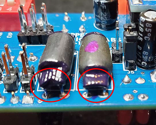
Thank you for the photos you emailed me. The optocouplers look mostly good, but there was one angle that kind of looked like they may need some more sealant. Here’s the edited photo…
https://zeppelindesignlabs.com/wp-content/uploads/2023/01/20230128_145356.png
…but if you tested them with your spotlight and they didn’t change resistance then they are probably sealed…but it would be good to be extra cautious in this matter just to rule out all the variables we can.
When I was designing the VPM-1 I looked into using the NSL-32 optocoupler, but it was hard to get consistent result from them…at least from the batch that I was testing. I ended up spending a couple of months developing my own rigorous test procedure for LDRs that we purchase in bulk. It ended up being way more reliable and economical for us to sort our own LDRs. But in looking at the datasheet for the NSL32SR2 (sorted) variety, they should be matched enough to work with the stereo VPM-1 (any type A-G). That’s assuming the datasheet is correct. I’ve often had a hard time getting the promised results from LDR datasheets in real-life situations. But if you have the sorted variety you can give them a try. It shouldn’t matter which optocoupler goes in which location, if they really do have those specs.
Good luck!
-BrachbrachModeratorCarlos,
Sorry for your stereo trouble.
First of all let me ask, when your VPM-1 kit came in the mail it should have had 2 pairs of LDRs in the stereo kit bag…did it also have one extra pair in the VPM-1 main kit? If so, which 2 of the 3 pairs did you use? We accidentally sent out 3 pairs of LDRs a few times, which can be confusing.
Second, did you make sure to change all 7 jumpers when running the stereo setup routine?
Third, it would help if I can see a picture of the plastic zip lock bags that the stereo LDRs came in. It would help for me to see how the numbers were written on the bags to know what generation of test LDRs were sorted. Could you please send me a photo of them to this address?:
info “at” zeppelindesignlabs “dot” com
Forth, it might be good to add some sticky tack (poster putty) on the ends of the optocouplers just to ensure they are really sealed. Sometimes if the holes are too big nail polish won’t seal them. Make sure you run the stereo setup routine again after you do that.
-BrachbrachModeratorGood luck! Let me know how it turns out.
-BrachbrachModeratorThe dip switches couldn’t directly be exchanged for pots, but the resistor networks attached to them could be (maybe that’s what you were referring to). You can see from the schematic that the resistors just create a low pass filter and a high pass filter, coupled with C2 and C3. So I suppose you could exchange the resistors for a 50k (or so) pot. You’d probably want to add a minimum resistance to keep the pot from going all the way to 0 ohms.
It is also possible to exchange the trim pots for external pots, if you wanted. I designed these features to “set and forget”, but if you wanted to play around with them more, I encourage you to experiment. The main issue might be the question of where to mount the pots on the enclosure. I don’t have any suggestions about this, so your guess is as good as mine.
Good luck.
-BrachbrachModeratorGreat! I’m glad to hear it’s working correctly now.
Enjoy!
-BrachbrachModeratorThe green LED issue must have happened when you pulled or replaced the LEDs. Do diode tests on all the pins of the RGB LED (the square pad is ground). The green pin is the one connected to R19 (the pin between the square pad and the pin closest to the ISP header). Use your continuity tester to check for shorts around the LED. You can also make sure the other side of R19 is going high when the green LED should be on.
Good luck.
-BrachbrachModeratorI would guess that it needs the stereo setup routine run. You also should re-calibrate it after doing any major change with the optocouplers. But this symptom could be caused by ambient light getting into one of the optocouplers. Just make sure there are no holes on the ends of either optocouplers that light can get in. If you aren’t sure, you might want to seal them (just to be safe) with something opaque (caulk, sticky-tack, opaque hot glue, etc…).
Good luck.
-BrachbrachModeratorGood! I’m glad to hear that.
Did you end up running the stereo setup procedure, or did you just fix the optocouplers? I’m just curious to know what the problem ended up being.
-Brach -
AuthorPosts
